I got a used Ortur Laser Master 2 quite a while ago. It's a laser diode set-up, typical of many such builds.
The version I got had poor cable management. The wires were put into a black spiral wrap, both along Y and X.
This is a write-up for how I set up a drag chain assembly for it. So far, I have the X axis pretty well done, and I just have to tighten up the Y axis.

Wiring
The Y axis carries three wire sets: X axis motor (4 wires), Y axis motor (4 wires), and a 4-wire assembly for GND, PWM, Laser +12v, and the X-axis left limit switch.
The X axis motor wires are longer, and feed through the Y-axis spiral wrap, and then into the X-axis spiral wrap. The black 4-wire assembly goes to a clamped PA2.0 header on a small board that is mounted at the leftmost point of the X-axis gantry. The board holds the limit switch, and then passes GND, PWM and +12v to a PH2.0 connector. That connector goes on to the laser head through the X-axis spiral wrap.
There have been at least a few YouTubes provided that show similar mechanisms for building a better drag chain assembly.
The one here from Chris Edwards was the first one I watched. He also apparently has a nicely built enclosure.
https://www.youtube.com/watch?v=qip0bX4TYcE
His approach to it use 3 foot, 1/8" aluminum angle for the X axis. Similar was done for the Y axis.
The X axis chain connected to a bent piece of aluminum and then to the motor.
A very similar solution was presented by wisam yousif at
https://www.youtube.com/watch?v=o8J8thwXq1Y
In his approach, the aluminum angle was cut and bent in a way that allowed it to be attached to the gantry.
In both examples, it was necessary to drill a hole in the gantry towers, and I wasn't up for doing that.
Wire management
In both examples, existing wire assemblies were extended. I found this to be necessary, too, mainly because there are clamping connectors used at different points of the existing assembly, and those take PA2.0 connectors.
Example:
https://www.amazon.com/Milkweed-Multi-Purpose-Connector-Crimping-Terminal/dp/B0CP8M7JHN?th=1
Most wiring is 24 gauge.
The YouTube examples showed ways of using low solder, heat-shrink connectors. I had some of those, but they're more meant for 22 gauge, not 24 gauge. Initially, I did offset cuts in the existing wiring, and tried extending using the connectors I had, but they were pretty stiff.
Instead, I ordered some 24 gauge wire that was already set up in a 4-wire assembly.
https://www.amazon.com/dp/B0CQVBJHN5?ref=ppx_yo2ov_dt_b_fed_asin_title
The wire ordering differed from the ones I had, but that wasn't a big deal.
I had existing PH2.0 connectors so instead of doing the offset-cut, low-heat-butt-weld approach, I used PH2.0 board headers and heat shrink. This was a little tricky, because the nylon header has a way of letting go of its pin under heat, so it works best if you set up a new connector first, insert it into the header, and then solder the wires to the header. That gives the heat somewhere to go, and keeps the pins straight.
I wasn't sure how much extra wire to add, so I ended up adding about 18" to each of the wire sets. That turns out to have been too much. But, it's not too hard for me to re-do the connectors, if I want, and that's way easier to adjust then if I were using the butt-weld connectors.
I extended the 4-black wire set with the butt-weld connectors in the earlier experiments, and I'm leaving that alone for now.
During all surgery, I tried to keep the X and Y axis motors unplugged. This would prevent back current from doing harm to the control boards. They should have protection for that, but I can't be sure if they do. After extending the wire sets, I tested the X and Y motors, and X-axis limit switch simply by turning on the machine. On boot-up the machine homes both axes.
I didn't yet test the laser, mainly because I've misplaced my safety glasses. The laser module stays unplugged until they're found.
Right side holder
For fear of wrecking up the existing gantry towers by drilling, I chose to make a clamp-on holder for the drag chain support.
I figured I could make something that mounts over the existing tower, and then has something that sticks out in the back. I could figure out the drag chain support bar from there.
That lead to the right side's "elephant". (Dessine-moi un mouton.)
The right tower is 5.6mm-thick plastic (presumably black acrylic) and roughly has 80-degree angles coming down to form a kind of trapezoid. There are upper screws, one holding the center of the gantry's 2020 extrusion, and the other attached to an L-bracket that also holds the 2020. The former also clamps the X axis toothed belt.
There are also two lower screws that hold the tower's wheel assembly.
I set up the right side of the model to go over the upper two screws and then extend outward a bit. Then, I made a similar structure that would wrap over the top of the tower. Finally, I added an inner wall that would go over the inner parts (in particular, the 2020 extrusion).
This was built in four pieces. The rightmost elephant was laser cut with thin ply (probably 2mm). I had other scrap ply that, when added up, would be at least 5.6mm thick, so I cut two of the "overwrap" inner piece. Then, I did the innermost piece from thin ply.
I had a piece of 1" wide, 1/8" thick flat aluminum laying about, so I used that to support the drag chain.
After a bit of experimentation and re-measuring, I chose to make the elephant have a hooked nose/trunk. Part of the placement was based on the left side's assembly, where the wire connection board is 20mm x 20mm, and at the same elevation as the 2020 extrusion. I dipped down 5mm below that for the channel, and then extended 2mm out and up. The rest is cosmetic.
 |
| Outer elephant wall |
 |
| Outer elephant (right side) side view |
 |
| View from behind, inside, overwrap atop black original tower |
 |
| View from behind, inside, inner hook, then overwrap, then elephant |
Left side holder
For the left side holder, I took advantage of the existing holes and spacers that keep the connector PCB attached to the tower. I detached the wire connectors from the headers, then removed the PCB and the stand-offs / spacers. The spacers are plastic cylinders, 5mm long, and they appear to serve two purposes: prevent the contact switch (X axis limit switch) solder points from touching the tower, and hold the PCB firmly in place.
The connector PCB is 20mm x 20mm.
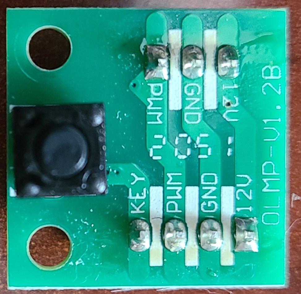 |
| Inside view of the connector PCB |
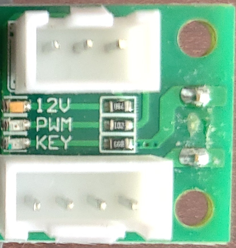 |
| Outside view of connector PCB |
The piece I built replaces the two nylon standoffs / spacers. It is meant to be cut from wood, and preserves the PCB hole spacing. There's also a cut-out area that keeps the board from interfering with the contact switch solder points.
I used the same dimensions as the left tower, putting the base of the 1/8" aluminum flat at 5mm below the PCB bottom, and extending outward 1" + 2mm. A little extra room is needed below the board so that the PA2.0 clip can work properly.

The left side hook

The hook mounted in place of the original PCB spacers

As a proof of concept, I just used binder clips to hold the elephant pieces together, and then did a test fit of the 1/8" aluminum flat. It fit perfectly.
From there, it was just a matter of marking, center-punching, and drilling holes to hold the drag chain.
Drag chain
The drag chain I got was a pair of 1 meter, 10x11, open, Type R18. The open assembly is really convenient for assembly and experimentation. The set came with endpoints and 3mm screws.
It takes a little practice but with a mini screwdriver, you can open the segments pretty easily.
 |
| Drag chain end screwed onto 1/8" aluminum flat |
The X axis drag chain, rear view, with laser head near right-most edge. The "elephant" is supporting the 1/8" aluminum flat. A binder clip is holding the pieces together (pre-glue-up phase).

Next steps
My next step will be to mount the Y axis drag chain to the underside of the 1/8" flat. I'm not sure if I'll spend the money to get another piece of aluminum to support the drag chain. I could get away with just letting it sit on the table. I also might opt to cut the support out of wood, rather than use aluminum, and maybe use dovetailing and wood glue to form an L. I'm also eyeing a piece of steel channel that was in the Cube Pro Duo. Yes, I think I'll use that.