Converting a typewriter to a teletype an impact printer
I don't really remember the origins of this project. What I've accomplished thus far really does not qualify as making a "teletype". What I have at this point is really an impact printer, since I'm not capturing keystrokes from the keyboard.From a historical perspective, I've always liked teletypes. Some of my earliest computing memories were playing games on teletypes at the Lawrence Hall of Science in Berkeley, CA. There, you could get a limited amount of time on one of their terminals, and play games like Trek and Hunt the Wumpus! And one of the more rewarding things to do was simply to print some ASCII art.
For this project, one path might have been that I bought a typewriter online with the intent to turn it into a teletype, and then found an explanation online. But it's more likely that it went the other way around: I found the explanation online, and then searched for and found exactly the same model of typewriter.
In any case, it starts with a Brother SX4000 electronic typewriter, and a nice write-up by numist.net.
This is the typewriter. I think I paid about $35 for it. It's rather bothersome that they list for much more than that on eBay nowadays. A few weeks back (August, 2019) I found another one, exactly the same model, at a nearby Goodwill for $15.


It's nice. And it's old, circa 2003. It has a daisywheel mechanism, which means there's a spinning plastic disk and each "petal" of the "daisy" has a character at the end. The wheel spins to the letter you want to type, a hammer whacks the letter against some ink ribbon, and the ink gets transferred to your paper.
The typewriter supports some unusual characters, like 1/2, 1/4, a +/- symbol, a degree symbol, a cent symbol, a paragraph symbol, and a section symbol. Some of those have interesting names in Unicode land. To me, they're so unusual that it's easier to type them as sequences of ASCII characters, rather than looking up their true symbolic representations in modern editing tools.
It also does not support some of what we'd consider standard characters today, including the caret "^", "squiggly braces" { and }, the pipe "|" symbol, and the backslash "\". Yes, that's a backslash. "Slash" is the forward-leaning thing "/" that we've had all along. As evidence, I submit this typewriter.
It has a "shift lock". Note that that's different from a "caps lock". If you engage the "shift lock", it shifts all characters, including numbers! That gets to be really annoying if you're trying to type on it, and you're used to today's "caps lock" behavior that only affects alphabetic letters.
There are three modifiers: SHIFT, CODE, and ALT. Those can be used in conjunction with some keys to type different letters are make the typewriter behave differently. Of interest are the CODE+O and CODE+P keystrokes, which are REV and INDEX, respectively. REV rolls the paper up a half line, and INDEX does the opposite. Along with the normal BACKSPACE, this allows me to combine multiple characters to create interesting effects.
The other neat thing about the SX4000 is that it's a portable typewriter. It has a non-detachable power cord with a little hole for the cord to go into. It has a covering case to keep dust from getting in. It has a handle so you can pick it up and walk around it with it (though that handle and its hinge pins are made of plastic). And it's fairly light, certainly lighter than the old Selectric tanks.
My initial goals were to print ASCII art, and it was important to me that the machine support BACKSPACE. There are ASCII art files out there, especially the ones I grew up with, where the teletype would print one character, step back, and then overstrike with another character to get a particular effect. I'm not quite sure where to find those. Googling "ASCII art with backspaces" doesn't really get me what I want.
Disassembly
The most nerve-wracking part about this project really was disassembling the case. There were two visible screws that were easily removed. Those sit behind the platen and are accessed from above. All the rest was held together by compression-type plastic clips and relied on the plasticity of the plastic to come apart. Coming at it blind, I didn't know whether top was clipped to bottom, or the opposite.Fortunately, there is a hole at the back right that houses the power cord. That served as a good starting point to get that first clip undone. With some wriggling and minor prying, the top came apart slightly from the bottom, and I was on my way. (Typical technique: wear eye protection, pry a section apart using one screwdriver, wriggle another screwdriver into place, push and pull until something pops apart, repeat.) Here's a picture of one of the clips.
Oriented normally, it looks like this (ASCII form)
|
|_ the clip
-/
--+
| the thing the clip hooks onto
|
So the top comes down and snicks down, hooking onto the bottom.
There are five of these clips along the thin, front edge plastic (just in front of the keys) and they point backwards.
 |
| Front-side clip (top of picture with hook shape) and receiver (bottom edge thing that has a rectangular hole in it) |
At the back, there are three clips. Each has two hooks and is about 1/2" wide. The first is around 1" from the left back, then about 4" spacing, another two-hook clip, 4" more spacing, and the final two-hook clip. Again, the the hooks point to the back.
 |
| Back side clip -- the thing with two hooks |
That means that the back clips are facing outward, and the front clips are facing inward.
For removal, I started at the back and very gently (but firmly) loosened the first one (back rightmost), probably by pushing inward along the top case edge, and pulling outward along the bottom case edge.
After the back edge was unclipped, and the two screws were removed, I unclipped the side clips. Those are visible and accessible within the carriage area. Turn off and unplug the machine, and manually slide the carriage to one end or the other to get access to the opposite side's clip. These are different from the rest. On each side of the top case, there is a plastic tongue with a hole. Normally, the tongue slips over a clip that protrudes from the bottom, and the clip clicks into the hole. To undo these, you have to gently pull the tip of the tongue inward (towards the center of the machine), while applying upward force to the case top.
Finally, the clips at the very front of the machine remain. Remember that these are along the weakest plastic section of the whole machine, so be gentle. On these, the clips are along the top and pointing inward, so you can defeat them by pushing the bottom case inward, and pressing outward along the case top, working from one side to the other.
As with any prying disassembly, wear eye protection, and consider using screwdrivers or other holders to keep the case parts separated, similar to how you might use tire irons to work a bike tire off its rim. With the kind of plastic used here, it's easy to mar the case, since it's so pliable. Be gentle. And don't be surprised if you break something.
With the case removed, the power supply in the back is exposed but the wiring remains enclosed or under the transformer board. Also, the holes that once held the screws are now exposed. To avoid losing those screws, I just put them back into the screw holes and gave them a few turns.
Here is a picture of the typewriter with the top case removed, but with the keyboard still in place.
 |
| Outer case removed, keyboard still in place |
The keyboard is also held down by clips. Here is an image of one of them.
 |
| Keyboard clip, bottom right |
There are only four. Each side has two: one near the edge in the front, and one at the bottom right/left side. I find it easiest to press outward on the rightmost one, and get it loose by lifting upward on the keyboard back at the same time. With that held partially unclipped, I can undo the bottom right one. That then lets me pivot the whole keyboard a bit, making it easier to do the bottom left one. The hardest to remove is the leftmost one. and get done with the bottom left, and then the left ones.
When you have those all unclipped, you can peek underneath to see how the keyboard is attached. Fortunately, it's not complicated. The keyboard attaches to internal circuitry at three points.
 |
| Keyboard lifted up to see what lies beneath |
Two of the connections are white wire cables that connect the LCD display to the circuit board. One is a 1x4 cable, and the other is 1x6. The headers on the PCB are the kind where they have a compression holder. You lift up on the white side that faces the typist and that allows you to wiggle the cable out. The "cables" end with multiple wires. The wires go into holes in the PCB header. But they are not keyed, so you can accidentally put them in backwards. I marked my headers and cables on one side with blue Sharpie to try to avoid putting them back in the wrong way.
 |
| White wire cable headers with blue Sharpie markings to remember orientation |
 |
| White wire cables unseated, wire ends visible |
The third connection is a one-sided, flexible flat ribbon cable with a 1x16 arrangement and 0.1" pitch.
 |
| Original flexible flat cable (FFC) inserted into a vertically mounted, through-hole header |
The PCB header is a spring-loaded set of pins, through-hole, vertically mounted. With care, you can just gently wiggle the ribbon cable out of the header, but be careful to avoid bending or breaking the ribbon, because if you do, you're probably SOL. The ribbon is unique to the machine, and you simply can't find things like them any more.
Here is a picture of the PCB with the keyboard removed.
 |
| Original circuit board, FFC and white cables and keyboard removed |
I was surprised at this point to see a flat-pack microcontroller in the typewriter. I didn't expect that kind of fine circuitry to be involved, given the product's age. I supposed I was expecting something clunkier.
The bottom black cylinder is a speaker/beeper.
The right, top header with orange and black wires is DC power coming from the transformer. I measured them, and they were delivering 8+ VDC (black negative, orange positive). The rest of the wires connect to the carriage and roller.
The carriage has a motor for rack-and-pinion linear motion left and right, a motor to spin the daisywheel, and a solenoid to whack a letter, but there's more than that. It also has to handle changes between ink and corrective tape, and manage point size changes. It has some mechanism for resetting the daisywheel, like it's using a limit switch. Also, upon full reset, it does some funny things where it pops the cartridge up and back down, and unlocking the carriage if it scrolls all the way left.
The roller motor control has to support bidirectional movement, given the REV and INDEX functions (and, obviously, a normal carriage return).
The keyboard
As mentioned earlier, the keyboard connects to the electronics via three ribbon cables. The two white cables strictly relate to the LCD panel. That helps the typist see status in various forms. The flexible flat cable is the one that provides information about all the keys, and one special pseudo-key, the limit switch on the left side.
 |
| Keyboard removed |
Once the keyboard is removed, you can see that it has a flat metal base that is, again, held on strictly by plastic compression clips. Beware of sharp edges along this base. Mine wasn't ground down along the edges, and that probably makes sense. These things weren't really meant for consumer interfacing.
 |
| Keyboard inverted, flat metal based clipped in place still |
Working from one side to the other, you can undo the clips and pull off the metal base plate.
 |
| Keyboard inverted, rotated 180, base metal plate tipped away |
 |
| Keyboard flexible circuit board exposed. White lines are facing up (in this perspective) and black traces facing down (in this perspective) are conductive. |
What's happening is that each key has a piece of conductive material at its base under a piece of springy rubber. When a key is pressed, a connection is made between two of the sixteen lines. It is all passive. I was hoping there would be power and ground, and some logic circuits converting values into ASCII or similar, but instead it's a bunch of physical switches. A quick resistance check found that each pad has around 300 ohms resistance.
Decoding the keyboard signals
My next step was to figure out a way to know which lines connected to which keys. For this, I used Adobe Photoshop Elements.I took my pictures of the original keyboard and the upside-down traces. The main layer of the photo was the right-side-up keyboard. I then used a second layer for the traces. I inverted the trace layer (flipped it horizontally) and then applied about a 50% transparency to the trace layer so I could see through to the actual keys. Then, I manually resized, rotated, and translated the trace layer so that the pads would align with the keys.

I then started using PSE's "magic wand" selection tool in Contiguous mode with various tolerance settings in an attempt to "select all similar white pixels" of each trace. This worked, mostly. There were lines that, due to contrast problems and photo lighting, didn't connect well. As I would select each trace, I would apply a color to it by using PSE's paint tool.
I think of the ribbon wires as being numbered from 1 to 16, with line 1 being at topmost ribbon trace when the keyboard is right-side up.
Here is an example of what I got when I had colored lines 9 and 16 orange and blue, respectively.
 |
| Initial line coloring using PSE |
A few things to note at this point: the 16-contact flexible flat cable is actually part of an entire flexible flat circuit board. It's not a separate FFC.
The keyboard circuit board is two-sided. The bottom side has the white traces that connect outward to the ribbon cable area. The top side has the contact switch and also has jumpers, which you can see as black segments bridging a white wire from one point to another. I don't know how they connect through. I get how plated through-hole works on normal PCBs, but this is some kind of through-plastic, through FFC, magic mojo.
The switches themselves are round, orange, rubber baby buggy bumpers with conductive, resistive material at the base. They appear to be glued onto the plastic.
I colored all lines, and then "drew" wire numbers to keep things straight. This is what it looks like, nearly complete. (This may yet contain a few errors.)
 |
| Full line coloring and numbering using PSE |
As examples, the left and right SHIFT keys are treated the same, both forming a connection between lines 1 and 16. A key press of the letter 'a' is detected when lines 2 and 14 form a connection.
There are a few odd optional contact switches on the far left side of the keyboard. They don't appear to serve any purpose.
The limit switch is the one at the top left. At boot-up, the carriage moves left, pushing against a lever which in turn forms a connection on lines 7 and 14. If you don't have the keyboard in the typewriter and turn it on, the carriage will move left and grind away until you turn the machine off. You can't just short these two, either. The boot-up sequence expects to move left, hit the limit, move right and the move right to see the limit switch release.
This is the limit switch lever and pad, shown from a different angle.

The key map
I laid out all the keys and their line pairs, and eventually found that every key press is based on a connection between something in traces 1..8 and something in traces 9..16.There are multiple switches connected to each line. For example, in the 1..8 range, contact 1 works in combination with contact...
9 = comma
10 = period
11 = 1/2 or 1/4 shifted
12 = semicolon or colon
13 = ] or [
14 = apostrophe or quotation mark
15 = space
16 = SHIFT
And similarly in the 9..16 range, contact 9 works in combination with contact...
1 = comma
2 = slash or question mark
3 = 1
4 = 3
5 = 7
6 = 5
7 = hyphen or underscore
8 = 9
Logically, it would only make sense for the typewriter to be doing some kind of iterative checking to see which lines were connected. It has to either sweep through lines 1..8, signaling each one at a time to make something happen as contacts 9..16 are inspected. Or, the opposite is happening: it sweeps through 9..16 iteratively, and while each is down, it checks to see if 1..8 is connected.
I took multiple stabs at finding out which were the scan lines and which weren't.
My initial assumption was that contacts 1..8 were the scan lines. I made the broad assumption that the ground line going in to the circuit board would be the same ground for everything, so I stripped a little of its shielding off. I could then set myself up with some alligator clips and patch wire to check each of contacts 1..8 using an oscilloscope.
The limit switch
In order to test contacts 1..8 on a scope, I would have to turn the typewriter on. So I did that and <<grrrrrind>> it sent the carriage left, trying to find the limit switch. Quick turn off the machine! When it does this movement, the carriage can do some weird things. It can pop the cartridge up to an odd height, or even lock the carriage into a clipped position on the left. (To unlock, turn off the machine, press the locking clip loose with a pen or pencil, and manually move the carriage to the right.)I knew already that lines 7 and 14, when connected, would fake a contact switch closure, so I had to wire those up separately. I picked up a random contact switch from the HackerLab electronics drawers, and soldered it on (normally open, contact on closure) with a 300 ohm resistor in series. Then, after turning the machine on, I would manually close the switch when it looked like the carriage was far enough to the left. As the carriage would then move right (presumably to find the point when the limit switch would release), I would let go of the switch button.
Later, when doing the "real" assembly, I kind of taped/glued the contact switch to the side of the typewriter interior such that the carriage would ram into it on startup. I got a little technical in doing this by measuring when the actual limit switch would hit, measuring the position of the carriage, and attempting to replicate that location with my own switch. What I ended up with was a good approximation: a chunk of a 3M Command Strip double-stick Velcro thing glued a lever-based contact switch to the left side.
Back to measuring the signals
With the machine on and the initial scoping set up, I tested all of lines 1..8, and found that they all registered high around 5v. They didn't show any indication of a periodic drop to ground.I then just put a voltmeter across the pins and found that lines 9..16 registered less than 5v, maybe around 4.6v, suggesting those were the scan lines. The lower average voltage would indicate a PWM-type behavior. I was expecting it to be about a 1/8th drop in voltage or 4.375v. In the end, it really should have been a 1/9th drop or 4.44v. But I am not entirely sure what I got at that point. I know for sure, though, that the value was less than on lines 1..8.
The breakout board
At this point, it was getting cumbersome to check the lines and the keyboard signals. I wanted to make by own breakout board that would let me "convert" the flexible flat cable into something where I could attach typical through-hole pitch headers.Unlike numist.net and another example I saw, I really didn't want to connect 30ga wire to available solder points on the circuit board. I just didn't trust my fine soldering skills (and/or my eyesight?) and didn't want to risk any damage to the board.
In my mind, I generally envisioned having a board set-up where
1. A substitute ribbon cable would come off the circuit board to mine, so I'd need a ribbon and a 1x16, 0.1", FFC header.
2. A 1x16 set of 0.1" pitch female headers would be available for inspecting what the circuit board was doing on each line.
3. I'd have a second FFC header so I could connect the original keyboard, if desired. In the end, I added this but haven't used it.
4. I'd have another 1x16 set of 0.1" pitch female headers to inspect what the keyboard was doing.
5. In-between the two FFC headers, I would either have straight jumpers or 300 ohm resistors for each bank of signals. The scan lines would have no resistance, but the "signal" lines (or "sense" lines) would have resistance similar to what the keyboard itself was generating on each key press.
The headers
Sourcing the 1x16, 0.1" FFC header was a challenge. FFC cables these days typically use 1mm or 0.5mm spacing. Having 0.1" pitch is old school. But, I did find it eventually: a "6-520315-6 TE Connectivity" header on mouser.com. I got that after applying the filters FFC/FPC/FFC & FPC Connectors, Number of Positions = 16, Pitch = 2.54mm, Termination Style = Through Hole, and Mounting Angle = Vertical. There also was a lot available on eBay -- 100 for about $20 -- if I wanted a bunch of them.I built the initial board just by using a plain old breadboard and doing a lot of solder bridging.
 |
| Breadboarded breakout board, front and back, allowing patch wire inspection of scan lines and signal lines |
The substitute ribbon cable (aka the Fake FFC)
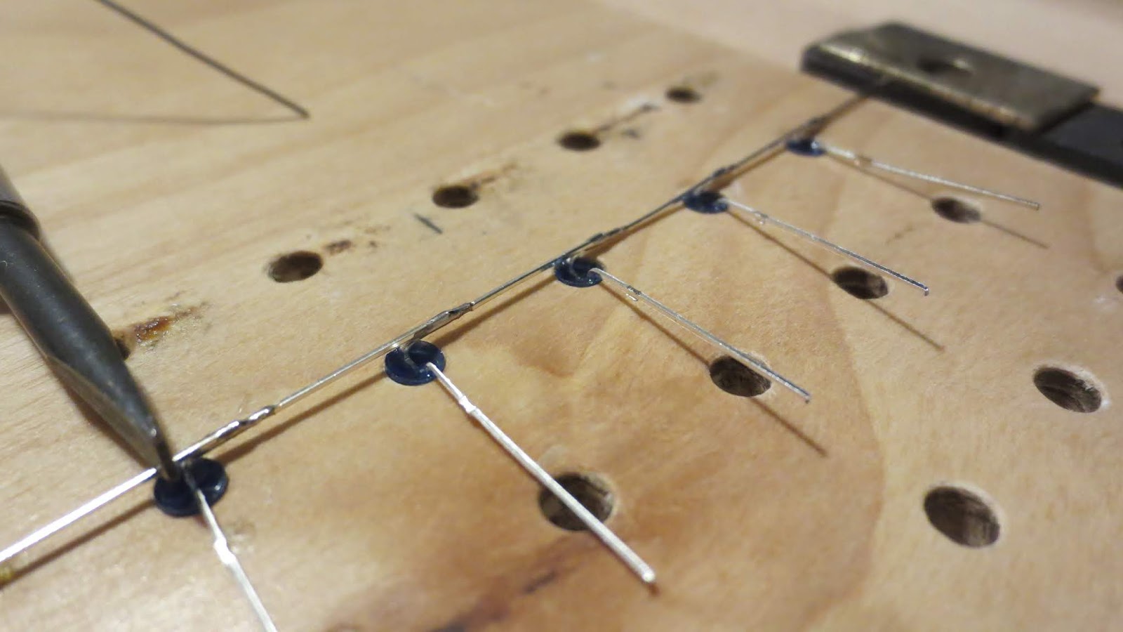
My next challenge was to create my own FFC 16-line, 0.1" ribbon cable. I noodled on this for quite a while. There are ways to make them the expensive way, using Kapton film coated with a copper layer, and then using chemical-based etching, but I didn't want to spend that kind of money.Fortunately for me, just a few days earlier, Jim S at the lab had shown me something he had built. He had used some copper tape as a common ground line for a device he'd put together. I hadn't seen copper tape and didn't know what it could do. But I found a small roll of it in the HackerLab drawers and, uh, rolled with the idea of using that tape for each of the 16 lines. The copper tape was 1/4" or 0.25" wide, and so I would need to cut strips lengthwise to end up with the "right" thickness. Given we had 0.1" pitch wires, each of my strips would need to be less than 0.1" so I settled on trying for a 0.6" width per line.
The plastic backing for the FFC was the next challenge. I would need something flexible and thin, but not too stiff, and non-conductive. Fortune again shone on the project. It was August, and it was back-to-school season. I went to the local Dollar Tree store, and got a pack of 3-ring binder index separators, basically five or six sheets of thin, transparent plastic. They were pretty close on stiffness/flexibility and perfect for thickness. Added bonus: I could choose from an assortment of colors.
 |
| Materials for fake FFC assembly |
Lining up the copper lines would be a challenge, so I just drew my 16 target lines in CorelDraw. I intended to make each line around 0.6" wide, but annoyingly, CorelDraw only let me specify the line width in "points". Assuming 72 (or is it 72.27?) points per inch I ended up using a 4.0-point line thickness, which computes out to about 0.055" wide. I modified the grid settings to align to a 0.1" pitch, just to visualize things. I also used a dashed line format to make it easier for taping. Once that was set up, I just printed it on normal paper.
 |
| PSE drawing of 4pt dashed lines, separated at 0.1" pitch |
I put the transparent index divider atop the paper, and cut out a chunk around the pattern, leaving a lot of excess on the width on the right side. That allowed me to tape the right edge temporarily (using plain old cellophane tape) in such a way that the tape would not interfere with the copper lines, but it would keep the plastic and paper together. The top, left, and bottom edges were trimmed exactly to the red lines.
At this point, I could start assembly. I would measure a piece of copper tape (with adhesive backing still in place) to be longer than the "ribbon" length to allow overlap on both ends. I would then cut lengthwise so that I would end up, hopefully, with something around a 0.04"-0.06" width. Then, I would undo the adhesive backing on one end, tape it down to the won't-stick-to-it-forever lab desktop, line it up with one of the ribbon lines, peel away the remaining backing, and press down. Each copper tape end would be folded over to the back of the plastic. Then, I would just use the back of a fingernail to smooth out any copper foil wrinkles.
With all the copper lines down, I trimmed the right edge to the red line, and in so doing I cut away the tape that was holding the paper to the plastic.
There were, of course, some mistakes made along the way, but they were pretty easy to correct. To be safe, I continuity-tested each pair of lines to make sure I didn't short anything.
When I was done, I wrapped up the copper side with more cellophane tape to prevent accidental electrical contact with anything else. I left enough exposed contact space at the end to fit into the FFC connectors. This actually worked out really well. Not only did the tape prevent electrical connection, it also added decent stiffness to the plastic, which by itself was a little too flexible for my tastes.
 |
| Fake FFC, front and back -- note inconsistency of copper tape cuts, how copper tape loops over ends to be conductive on both sides, and cellophane tape usage to insulate and stiffen |
Happily, this put me back to a point where I had a breakout board connected to the typewriter circuit board.
 |
| Breakout board attached, but bad design prevents access to headers |
I realized too late that the placement of the female header pins was totally inconvenient. It would have been better to have had them on the "inside" part of the board, because at this point the ribbon was interfering with access.
I also realized too late that I wanted specific breakout lines for the limit switch. I hacked in some patch wires for lines 7 and 14, and solder-bridged them. (Those are the white wires and the contact switch shown in the picture above.)
In the end, I got a decent breakout board, and I know how I'd make a better one next time.
Back to the testing the electronic signals
At this point, I had a breakout board connected by fake FFC to the original circuit board, and a hacked-in limit switch. The machine could be booted up without the original keyboard, as long as I clicked and unclicked the switch at the right times.I broke out my oscilloscope and took a look at the various lines after booting up. There, plain as day, I could see the signal drops along lines 9..16. They would stay high most of the time, then drop down for about 2ms, and then go high again. I only had two lines on my scope but with iterative checking, I could see that the 2ms low period would apply to pin 9, then 10, then 11, and so on, until pin 16 went low.

However, after pin 16 went high, all of the 9..16 lines would stay high for 2ms until pin 9 would go low again. So that meant that the total period of scanline activity was not 8 x 2ms, but 9 x 2ms.
That also meant I would have 2 ms to do something to trigger key and modifier presses while a given scan line was down. And I didn't have an example of what the keyboard would actually do with a real key press.
How would I actually "connect" a pair of wires to simulate a key press? For example, if I were to try to connect 7 and 11 for a letter "n", I would have to have an electronically controlled switch for that line combination, and trigger it from a microcontroller. For a basic test of this, I wired in a basic BJT transistor (with appropriate pull-ups and base resistor), tested it in isolation, and then connected lines 7 and 11 to either end. I tried triggering that manually, and got nothing from the typewriter. I also considered using an optocoupler, but if a transistor wasn't working, and opto wouldn't.
After several frustrated attempts, I chose to do the brute force and semi-dangerous thing -- I just put a patch wire into line 11 and touched (no resistor) it to GND. The typewriter sprang to life and jammed out several characters at once: 1/2, q, e, t, o, u, n, v, or a subset of that sequence. So that meant the typewriter was working, and it was handling the scanline 11 with sense lines 1..8 in that order, but for some reason I could not trigger it that way electronically.
I didn't really want to, but I went ahead and directly connected Arduino Mega 2560 lines to scan lines and sense lines. I wrote a quick sketch to look for a drop on a given scan line, and had that fire off a drop on a sense line. Nothing. (This was a bit of a dangerous test, not knowing the current draw of each line.)
I did similar testing using a Saleae 16-pin logic analyzer that Jim let me borrow. Sure enough, I could see the drop of the scanline, and I could see the drop on the sense line, but no activity came from the typewriter.
Saleae screenshot. Channel 1 is the scan line, Channel 3 is the sense line. Channel 3 goes low for a delayMicroseconds(1800) == 1.8ms period. However, no character is printed.

I tried tightening up the code. Maybe the delay between the sense line trigger point and the sense line drop point was a problem. No luck. (Typical delays, like Serial operations, were removed. Also, I tried switching from the slooow digitalWrite function to using direct bit setting, specific to the Mega2560 internal chip.)
I tried dropping the sense line low longer than the duration of the 2ms scan line down time. I thought, maybe if I'm too late generating the sense line pulse, I'll start off with it low going into the next scan line. Still nothing.
(Here, channel 1 is scan line, channel 3 is sense line. Sense line overshoots scan line pulse by 442 usecs.)

Around this time, I finally gave in and started looking at numist.net's code for ideas.
One thing that came up was that I should simulate holding the key press down for more than a single scan line pulse. The onboard circuitry may be using that as a debounce indication, or some such. I also, at this point, started experimenting with having the Arduino pulse control a transistor to separate out the current flow.
So in this shot, we have channel 3 as the scan line, channel 1 as the Arduino high signal controlling a transistor, and channel 0 as the transistor's output, tied to the sense line. I pretend the key is held down by pulsing across four consecutive scan lines. Still nothing.

In this latest attempt, I was triggering the sense line 24 usecs after the scan line low state was detected. I was using digitalRead() to see the scan line, and digitalWrite to set the sense line.
To tighten that up, I went to direct port manipulation on write. I left the read function as it was. Using PORTC on an Arduino Mega2560, I would be able to change the bit state on all eight sense lines in a single byte write. But it also meant that I would have to re-wire my pins as
a8 = pc0 = digital37
a9 = pc1 = digital36
a10 = pc2 = digital35
a11 = pc3 = digital34
a12 = pc4 = digital33
a13 = pc5 = digital32
a14 = pc6 = digital31
a15 = pc7 = digital30
(Ref: https://www.arduino.cc/en/uploads/Hacking/PinMap2560big.png)
Unfortunately due to physical layout, that meant the sense pins would be sort of upside-down compared to what I wanted. No matter, I went ahead and wired it that way and adjusted the code. To do that, I also went to using DDRC to set all sense lines as output pins in one go.
This brought the delay time down to 12 usecs instead of 24 usecs.

But it still didn't generate a typed character.
Help!!!
At this point, I finally had to give up and go to the cheat page to figure out why I wasn't getting a printed character. I visited numist.net's page, and then pored over the related Arduino code to get ideas. A bit at a time, I adapted things and suddenly I was getting characters!There were several magic tricks to it.
First, the numist.net page indicated that current draw along any line was a mere 9 mA, well within the safety zone for an Arduino output pin. As such, I didn't have to do any trickery with transistors or optocouplers.
Second, the code was using direct port manipulation to read and write pin values. I had adapted to using the write portion, greatly reducing the time between the sync line high-low transition and my sense line high-low setting. I ended up not needing to do direct port reads to see the scan lines.
Third, the code would raise all output lines high upon seeing a scan line going low. I don't think that really triggers anything. After all, all sense lines would be high anyway during a period of keyboard inactivity, and I wasn't seeing typing in my earlier tests. Still, I went ahead and adopted the "set all lines high" approach.
Fourth, and possibly most importantly, the numist.net code would set a signal / sense line low multiple consecutive times. I had tried that before to no avail, but at that time I didn't have all the lines connected, and I might have floated some lines, so maybe that influenced the behavior. After some experimentation, I found that it only required two consecutive iterations to work. That meant for any lower case character, I would use (8 scanlines + 1 unused) x 2ms x 2 iterations, or 36 ms to get an unmodified character communication done.
Given all that, I rearranged my code a bit, and much to my surprise and relief, the typewriter whacked a letter onto the paper!
After a few more iterations, I was able to use modifiers, too. I had thought that I could just jam in the modifier behavior in the same data set as the keys, but it actually required me to simulate the modifier down, repeat on the next cycle, then add the key down, and repeat again another cycle. So, modified keys would take 72 ms (four cycles, 18ms apiece) to go out.
Software
I built this using an Arduino Mega2560. I chose that because it had lots of output pins.The setup() function of the sketch precomputes all the scanline bytes for each character. Each character is represented by a 16-bit quantity with the low 8 bits representing signal line values (active low), and the high 8 bits representing scanline match. Given the example above where 'a' is scan line 14 and signal 2, the signals array would be set up as
signals['a'] = (1<<(2-1)) | (1<<(14-1));
Later, I could take that value and split it apart like this:
signalBits = signals['a'] & 0xff;
scanBits = signals['a'] & 0xff00;
Then, I could "not" the signalLine value to drop a particular value low (signalBits = ~signalBits;).
As for scan lines, I was iterating in a loop anyway, waiting for a line to go low, so I could set up a mask bit and compare against it with each line I was looking for. Conceptually, something like this:
scanMask = 0x01;
scanLine = 9;
if (digitalRead(scanLine) was high and is low now) {
scanLine++;
if (scanBits & scanMask) {
PORTC = 0xFF; // force all signal lines high
PORTC = scanBits; maybe delayMicroseconds here
}
scanMask <<= 1;
}
if (scanLine == 17) {
// we're done with this character
}
And then other trickiness would be set up to handle modifiers.
The loop() for the sketch basically runs a state machine. The states:
1. Wait for a character to print. In early code form, I just hardcoded a single character to repeat every few seconds. Later, I made the code read frequently from the Serial input line. If there is no character to print, wait some significant amount, like 50ms.
2. Prepare signals Get the precomputed signal values and scan line information for the character and modifiers in question. In early form, I set up the character signals at the same time as the modifier signals, thinking both could be sent in and be recognized. But instead based on numist.net, I found that I had to send the modifiers for a few cycles on their own, and then send the character with modifiers. In retrospect, this "state 2" could have been split into a "send modifiers" state first, and then a "send character signal with modifier signal" state.
3. Once the signals are set up, I am in wait state, looking for a low signal, starting with line 9. Upon seeing that, I set PORTC to 0xFF to force all lines high. Then, I grab the precomputed signal value (bytes[9], initially) and put that value into PORTC, thus setting all values for lines 1..8 that are appropriate when scan line 9 is down. The values going into lines 1..8 are always default high, active low.
After this, I might wait a very small amount of time (delayMicroseconds) to let the controller see my signal lines.
Then I iterate on each subsequent scan line.
If the overall process of sending a batch of 8 signal lines takes more than 2ms, I'm screwed. But it runs quite quickly.
4. After line 16 is done, I return to state #3 for any iterations of modifier-only signals or character+modifier repetition. Then, when that's all done, I return to state #1.
Conceptually, my code is similar to what numist.net did. The numist.net code does all character set-up in the 2ms high time (after scan line 16 goes low-to-high and before scan line 9 goes high-to-low). My state machine allows me to set up the output line bytes at any time before scan line 9 goes low.
Driver software
Unfortunately, the Arduino Mega2560 does not support native XON/XOFF flow control. I was too lazy to do that myself, so I wrote a Python program and had it set up with timing delays between characters. The carriage return would be given special treatment, delaying 1.5s after that was sent.More physical build
As it turns out, my ribbon length was long enough for me to be able to put everything under the original keyboard. The limit switch was glued to the far left. Just inside of that was my breakout board, followed by the fake FFC, and the original circuit board. To the right of all that, I put in the Arduino. This meant having long patch wires stretching from the breadboard over the original PCB to the Arduino, but it did reach, and no one would know.The original transformed DC voltage was coming in around +8VDC, so I was able to tap into both the high and low lines for that, and plug them in to Vin and GND, respectively, on the Arduino. I haven't seen any ill effects of having the Arduino and original circuit board drawing power at the same time, but bear in mind that my current configuration has disabled the LCD display panel. The power lines still continue onward to provide power to the original circuit board.

The original case has a little cut-out rectangle on the interior of the cord storage area! That was quite a fortunate thing. That allowed me to connected a USB-A cable to the Arduino, and tuck it in along the side of the box, flowing it outward near the 110VAC cord. So, while not properly secured with strain relief, etc., etc., it meant that I could mostly close up the case while still having an Arduino programming and communications path. (If that didn't work, I would consider adding a bluetooth board or something like that.)

Gotchas
Carriage returns on PCs are implemented using character 10, which technically is a "line feed" character. When you edit a text file in Windows, the file already magically knows whether or not it's Unix-based (CRLF = both chars 13 and 10) or Windows-based (CR = char 10 on its own). To treat them the same, I made the Arduino code recognize char 10 as a carriage return, and ignore char 13.Arduino has problems with memory usage. In my case, I didn't have to use the PROGMEM construct, but if you use more memory, you could start to see very random crashes. Numist.net referred to this. In my case, I didn't have to use PROGMEM.
The machine gets very confused if I have the Arduino connected to my PC via USB at the same time as when I'm booting up the typewriter. My implementation causes the 7 and 14 lines to be high, thus blinding the system to the real state of the limit switch. I'm in the habit now of unplugging USB, then turning on the machine, then letting it find the limit switch, then plugging in the USB. If you get the sequence wrong, you can start over, and the machine will correct itself.
If you run the machine and start getting really weird characters, it's possible that the full boot sequence wasn't done, and the daisywheel didn't reset its orientation. Do what a tech support person might tell you to do: remove the USB cable, power off the typewriter, and power it back on again, and see if that solves the problem. In my experience, a reboot works -- not just for this typewriter but for a host of tech ailments.
Conclusion
I couldn't have done this without the existing code from numist.net. Or, at least that saved me a bunch of time so I didn't have to sniff the actual signals emitted during a real key press.In doing this project, I also found out rather accidentally that I'm 2 degrees of separation from numist.net in real life.
My initial goal was to make a teletype. I'm only half way there. At this point, I only have an impact printer. But it's still totally satisfying to see it work.
I'm disappointed in the Arduino lack of XON/XOFF protocol support. I could implement that myself, and it's possible it's available in a SoftwareSerial implementation, but it's not really worth the effort.
Next steps
I'd like write some software that generates the right text patterns for printing a grayscale image. I'm sure others have done this, but for my purposes I'd like to do it in such a way that it is limited to the specific characters that this typewriter prints, and it takes advantage of the backspace, half backspace, REV, and INDEX functions natively supported by the typerwriter.I'm also curious what it would take to 3d-print my own ABS daisywheel. Ooo, and for that matter, what if the daisywheel itself were to print pixel patterns? That's a head trip, innit?
Arduino sketch code
// This work is licensed under the Creative Commons Attribution-ShareAlike 3.0 Unported License. To view a copy of this license, visit http://creativecommons.org/licenses/by-sa/3.0/ or send a letter to Creative Commons, PO Box 1866, Mountain View, CA 94042, USA.
// teletype
//
// This is Dave's hack project modifying a Brother SX4000 typewriter so that it's controlled
// by Arduino. This is an output-only project.
//
// Credit to numist.net for his work on this ca. 2010. He has much tighter code for
// this, and it handles both inputs and outputs.
//
// Much of this project was created separate from the Numist.net work. The keyboard mappings
// were constructed based on direct analysis of the device's keyboard circuitry.
// The rough idea of scanline and signal (sense) circuitry was implied by the keyboard
// switch layout, but I probably gleaned some of the concept from Numist.net when I read
// about this several years ago.
//
// The main areas where I benefitted from Numist.net:
// 1. There appears to be a need to repeat signals at least twice
// 2. Modifiers appears to have to be sent in solo before modified chars.
// 3. It appears you have to set all sense lines high before dropping any low.
// 4. Using direct pin mappings for sense line writes
// Where my code differs from numist.net
// 1. Conceptually I have a state machine with three main states
// 2. My layout of the keyboard mappings is different than his.
// 3. I'm still using individual pin inputs for scan lines. I could switch, just haven't done so.
// 4. I support ctrl+H and half-backfeed (superscripting). I dunno, maybe he does, too.
// 5. Mine was made 9 years after he was done.
// 6. Mine is specifically for ATMega2560.
// 7. Mine tries to handle the limit switch specially. (I found that due to combination
// sense 7 / scan 14,
// if I set 7 initially as an OUTPUT pin, I plow over what the actual limit switch is trying
// to indicate, mine being high when they try to show low, and thus I disable the switch.
// So, on boot-up, I set that as an INPUT pin until the system quiesces.
// That also assumes my Arduino will be activated when the typewriter boots up.
// If for some reason the typewriter seeks the limit switch some time after boot,
// then it might grind.)
unsigned char outbuf[80];
unsigned char* outbufPtr = outbuf;
unsigned char charToPrep = 'a';
unsigned char lastCharOut = 0;
#define STATE_WAIT_FOR_CHAR 0
#define STATE_PREP_PINS 1
#define STATE_WRITE_PINS 2
int curState = STATE_WAIT_FOR_CHAR;
int oldScanLineState = HIGH;
int newScanLineState = HIGH;
int modOnlyIterations = 0;
int totalIterations = 0;
int outCycleCounter = 0;
// This is how "long" we hold the key down while writing.
// In clock time, this is n * 18ms since each sequence
// of the scanline scans is 8 pins x 2ms plus 2ms high.
// I am doing this because numist.net did this, and
// when I only had one iteration, nothing was typed.
// So I'm hoping having multiple iterations of the same
// letter (kind of a press and hold, but short) does something
/// magic to make the system recognize the key press.
//
#define KEY_PRESS_ITERATIONS 2
// The typewriter does not react if KEY_PRESS_ITERATIONS is 1
// This section lays out the mapping of keyboard
// ribbon pins to Arduino Mega2560 pins, so I can
// address them by typewriter keyboard name.
// K01 is top left of keyboard, and is the first
// of the K01..K08 "sense" pin set.
// K09..K16 is the "scanline" pin set, the ones
// that the keyboard circuit drops low for 2ms
// at a time to try to trigger a low connection
// across a typewriter keyboard physical switch.
#define K16 53
#define K15 51
#define K14 49
#define K13 47
#define K12 45
#define K11 43
#define K10 41
#define K09 39
// K01..K08 aren't used any more since I switched to using DDRC and PORTC on Mega2560.
// But it doesn't hurt to document the layout here.
// They do go in the reverse order compared to scanlines -- just the way it worked out.
#define K08 30
#define K07 31
#define K06 32
#define K05 33
#define K04 34
#define K03 35
#define K02 36
#define K01 37
// bytes is an array of values indicating what I'll
// use for pins 1..8 when a given scanLine goes low.
// The sense pin values are stored in bytes[9..16]
// so when scanline 9 goes low, I can just choose the
// precomputed value of bytes[9] without offsets
// for simplicity. So unlike other arrays, bytes
// is allocated to allow values 9..16 as indexes,
// hence it is 17 bytes in size.
// modOnlyBytes was added afterward. That allows me to
// send only the mod byte values in lead-up to sending
// the signals for the modified characters. The easiest
// thing to do was to mirror existing bytes[]-oriented
// code and make the "bits to send" just source from a
// different place during a lead-up period.
unsigned char bytes[17];
unsigned char modOnlyBytes[17];
unsigned char *curBytePtr = 0;
unsigned char *curModOnlyBytePtr = 0;
// bitmaps contain 8-bit values representing the
// values 1..8 (3 bits) for which scanline is held
// low for a given key, and 1..8 (3 bits) for which
// sense line is triggered low when the scanline is low.
// Each byte value in bitmaps has sense line in the low
// 4 bits, and scanline in the high 4 bits.
unsigned char bitmaps[256];
// modifiers contains a bitwise value of 1, 2, or 4
// to indicate whether the shift, alt, or code key
// must be held down simultaneously with a key in order
// to get a particular key emitted. For example,
// a capital A not only is indicated by the scanline/
// sense line values in bitmaps['A'], but also must be
// accompanied by a MOD_SHIFT value in modifiers['A']
unsigned char modifiers[256];
#define MOD_NONE 0
#define MOD_SHIFT 1
#define MOD_ALT 2
#define MOD_CODE 4
// sensePins and scanPins are ways
// for me to loop through the sense and scan pins
// one at a time without naming them by name.
//int sensePins[8];
// Sense pins are now PORTC
// bit 0 is pin 37, bit 7 is pin 30
// so if I put a MSB sense pin byte into PORTC
// then its lowest bit (what was sense 1)
// is now in 37, and its highest bit (what was sense 8)
// is now in 30. Physically, this is using the second
// column of pins and in reverse order of what I was doing.
//
// For testing, sense 2 is now pin 36.
int scanPins[8];
// Sense lines trigger 2n2222 transistor
// to allow ground current to flow cleanly to
// kbd circuit board now, so a LOW does not saturate
// and a HIGH does.
// For that reason, too, sense pin 7 is a PULLDOWN
// on startup, not a PULLUP.??? Or should I control
// that using some other special mechanism?
#define SENSE_DEFAULT LOW
#define SENSE_TRIGGER HIGH
// curScanLine is used in the WRITE state to check
// each scanline for a high-low transition.
// It's meant to march through values 9..16
// so it's numeric keyboard pin values.
int curScanLine = 9;
int charRepeatCount = 0;
// if charRepeatCount is 1 or more when entering handleWaitForChar,
// it just re-uses the last determined charToPrep for output and continues
// to typing, decrementing charRepeatCount. if charRepeatCount is zero,
// it pulls something into charToPrep using its normal means (e.g.,
// read from a static buffer, get char from Serial).
// .
void setup()
{
Serial.begin(9600);
// To send a file using Windows cmd, try
// mode COM21 BAUD=9600 PARITY=n DATA=8 XON=on
// copy yourfile.txt /B \\.\COM21 /B
// sensePins[0] = K01;
// sensePins[1] = K02;
// sensePins[2] = K03;
// sensePins[3] = K04;
// sensePins[4] = K05;
// sensePins[5] = K06;
// sensePins[6] = K07;
// sensePins[7] = K08;
scanPins[0] = K09;
scanPins[1] = K10;
scanPins[2] = K11;
scanPins[3] = K12;
scanPins[4] = K13;
scanPins[5] = K14;
scanPins[6] = K15;
scanPins[7] = K16;
memset(bitmaps,0,256);
memset(modifiers,0,256);
// Map ctrl-H to backspace half. Other code will have to run that twice
// to get a full backspace.
// bitmaps[0x08] = 4 | ( 15 << 4 ); modifiers[0x08] = MOD_CODE;
// Machine has both a 4/15+CODE (half BS) and 6/15+NONE (full backspace).
// I just need the full BS and won't need to implement char repeat function.
bitmaps[0x08] = 6 | ( 15 << 4 );
// Faked chars 30 and 31 to support REV and INDEX command.
// REV is a roll up 1/2 line command
// INDEX -- well, I think that's un-REV, I hope
// (Per SX4000 manual)
// REV (code+oh) = lower the paper a half line
// INDEX (code+p) = raise the paper a half line
bitmaps[30] = 5 | ( 11 << 4 ); modifiers[30] = MOD_CODE;
bitmaps[31] = 5 | ( 13 << 4 ); modifiers[31] = MOD_CODE;
bitmaps['1'] = 3 | ( 9 << 4 );
bitmaps['2'] = 3 | ( 10 << 4 );
bitmaps['3'] = 4 | ( 9 << 4 );
bitmaps['4'] = 4 | ( 10 << 4 );
bitmaps['5'] = 6 | ( 9 << 4 );
bitmaps['6'] = 6 | ( 10 << 4 );
bitmaps['7'] = 5 | ( 9 << 4 );
bitmaps['8'] = 5 | ( 10 << 4 );
bitmaps['9'] = 8 | ( 9 << 4 );
bitmaps['0'] = 8 | ( 10 << 4 );
bitmaps['!'] = 3 | ( 9 << 4 ); modifiers['!'] = MOD_SHIFT;
bitmaps['@'] = 3 | ( 10 << 4 ); modifiers['@'] = MOD_SHIFT;
bitmaps['#'] = 4 | ( 9 << 4 ); modifiers['#'] = MOD_SHIFT;
bitmaps['$'] = 4 | ( 10 << 4 ); modifiers['$'] = MOD_SHIFT;
bitmaps['%'] = 6 | ( 9 << 4 ); modifiers['%'] = MOD_SHIFT;
// bitmaps['6'] = 6 | ( 9 << 4 ); cent
bitmaps['&'] = 5 | ( 9 << 4 ); modifiers['&'] = MOD_SHIFT;
bitmaps['*'] = 5 | ( 10 << 4 ); modifiers['*'] = MOD_SHIFT;
bitmaps['('] = 8 | ( 9 << 4 ); modifiers['('] = MOD_SHIFT;
bitmaps[')'] = 8 | ( 10 << 4 ); modifiers[')'] = MOD_SHIFT;
bitmaps['-'] = 7 | ( 9 << 4 );
bitmaps['_'] = 7 | ( 9 << 4 ); modifiers['_'] = MOD_SHIFT;
bitmaps['='] = 7 | ( 10 << 4 );
bitmaps['+'] = 7 | ( 10 << 4 ); modifiers['+'] = MOD_SHIFT;
bitmaps['q'] = 2 | ( 11 << 4 );
bitmaps['w'] = 2 | ( 13 << 4 );
bitmaps['e'] = 3 | ( 11 << 4 );
bitmaps['r'] = 3 | ( 13 << 4 );
bitmaps['t'] = 4 | ( 11 << 4 );
bitmaps['y'] = 4 | ( 13 << 4 );
bitmaps['u'] = 6 | ( 11 << 4 );
bitmaps['i'] = 6 | ( 13 << 4 );
bitmaps['o'] = 5 | ( 11 << 4 );
bitmaps['p'] = 5 | ( 13 << 4 );
bitmaps['['] = 1 | ( 13 << 4 ); modifiers['['] = MOD_SHIFT;
bitmaps[']'] = 1 | ( 13 << 4 );
bitmaps['a'] = 2 | ( 14 << 4 );
bitmaps['s'] = 5 | ( 12 << 4 );
bitmaps['d'] = 5 | ( 14 << 4 );
bitmaps['f'] = 3 | ( 12 << 4 );
bitmaps['g'] = 3 | ( 14 << 4 );
bitmaps['h'] = 4 | ( 12 << 4 );
bitmaps['j'] = 4 | ( 14 << 4 );
bitmaps['k'] = 6 | ( 12 << 4 );
bitmaps['l'] = 6 | ( 14 << 4 );
bitmaps[';'] = 1 | ( 12 << 4 );
bitmaps[':'] = 1 | ( 12 << 4 ); modifiers[':'] = MOD_SHIFT;
bitmaps['\''] = 1 | ( 14 << 4 );
bitmaps['"'] = 1 | ( 14 << 4 ); modifiers['"'] = MOD_SHIFT;
bitmaps[0x0a] = 2 | ( 15 << 4 ); // Treat LF as a carriage return+LF. Ignore 0x0d
bitmaps['z'] = 2 | ( 12 << 4 );
bitmaps['x'] = 7 | ( 12 << 4 );
bitmaps['c'] = 8 | ( 12 << 4 );
bitmaps['v'] = 8 | ( 11 << 4 );
bitmaps['b'] = 8 | ( 13 << 4 );
bitmaps['n'] = 7 | ( 11 << 4 );
bitmaps['m'] = 7 | ( 13 << 4 );
bitmaps[','] = 1 | ( 9 << 4 );
bitmaps['.'] = 1 | ( 10 << 4 );
bitmaps['/'] = 2 | ( 9 << 4 );
bitmaps['?'] = 2 | ( 9 << 4 ); modifiers['?'] = MOD_SHIFT;
bitmaps[' '] = 1 | ( 15 << 4 );
bitmaps['<'] = 2 | ( 13 << 4 ); modifiers['<'] = MOD_CODE;
bitmaps['>'] = 6 | ( 11 << 4 ); modifiers['>'] = MOD_CODE;
for (int i='a'; i<='z'; i++)
{
int v = i-'a'+'A';
bitmaps[v] = bitmaps[i];
modifiers[v] = MOD_SHIFT;
}
// Pre-set the sense pins HIGH.
// We draw them low as typing occurs.
// But on boot-up, we don't want them to
// be in a low state when we set the pins
// to OUTPUT mode.
// for (int j=0; j<8; j++)
// {
// digitalWrite(sensePins[j], SENSE_DEFAULT);
// }
PORTC = 0xFF; // Default everything "high".
// ref https://forum.arduino.cc/index.php?topic=173099.0
// I want to default output pins to HIGH before
// turning on pinMode to avoid an accidental startup
// condition, since output pins default LOW.
//
// Pin 7 gets special treatment for the boot period
// so that the carriage can auto-seek and not
// conflict with the Arduino's use of the pin.
// After initial start-up, pin 7 will be disconnected
// by the limit switch, so I can regain control.
// for (int j=0; j<8; j++)
// {
// if (sensePins[j] == K07)
// {
// pinMode(sensePins[j], INPUT);
// } else {
// pinMode(sensePins[j], OUTPUT);
// }
// }
// K07 is sense pin #6 in range of 0..7
DDRC = 0B10111111;
for (int j=0; j<8; j++)
{
pinMode(scanPins[j], INPUT_PULLUP);
}
delay(5000);
// Serial.println("starting");
// Assuming carriage did seek operation within
// 15 seconds of Arduino start-up, now it's safe
// to use K07 for output.
PORTC = 0xFF;
DDRC |= 0B01000000; // turn sense 6 to output
// digitalWrite(K07, HIGH);
// pinMode(K07,OUTPUT);
outbuf[0] = 0;
// strcpy((char *)outbuf,"1234567890\r!@#$%^&*()"); // not cool cast
// strcpy((char *)outbuf,"abcdefghijklmnopqrstuvwxyz"); // not cool cast // works
// strcpy((char *)outbuf,"ABCDEFGHIJKLMNOPQRSTUVWXYZ");
// int len = 0;
// strcpy((char *)outbuf, "Inte");
// len = strlen((char *)outbuf);
// outbuf[len++] = 8;
// len = strlen((char *)outbuf);
// outbuf[len++] = '\'';
// strcpy((char *)outbuf+len,"ressan");
// len = strlen((char *)outbuf);
// outbuf[len++] = 8;
// len = strlen((char *)outbuf);
// outbuf[len++] = 30; // Faked char for REV to superscript next char
// len = strlen((char *)outbuf);
// outbuf[len++] = '-'; // There is no tilde, superscript a hyphen?
// len = strlen((char *)outbuf);
// outbuf[len++] = 31; // Faked char for INDEX to un-superscript next char
// strcpy((char *)outbuf+len,"t 0");
// len = strlen((char *)outbuf);
// outbuf[len++] = 8;
// strcpy((char *)outbuf+len,"/");
// Part of doing the strcpy above is that it adds a terminating 0 byte
curState = STATE_WAIT_FOR_CHAR;
}
void handleWaitForChar() {
// Serial.println("Wait for char");
// This chunk of code is set up as its own state
// to allow future management of serial IO or some such.
// For now, it just loops through a fixed array of chars
// to print.
#ifdef SUPPORT_REPEAT
if (charRepeatCount > 0) {
--charRepeatCount;
curState = STATE_PREP_PINS;
} else {
#endif
if (Serial.available()) {
int c = Serial.read();
if (c == 0x0d) return; // ignore CR. Support LF (0x0a) (10) only.
charToPrep = c;
if (charToPrep == lastCharOut) {
delay(36); // let two passes of scanlines go by so it doesn't look like key was held down
}
outbuf[0] = c;
outbuf[1] = 0;
outbufPtr = outbuf;
}
if (*outbufPtr) {
charToPrep = *outbufPtr++;
// If it's not a mapped char, then use '?'
if (!bitmaps[charToPrep]) {
charToPrep = '?';
}
// Serial.print("Ready to prep pins for ");
// Serial.println(charToPrep);
curState = STATE_PREP_PINS;
#ifdef SUPPORT_REPEAT
charRepeatCount = (charToPrep == 0x08)?1:0; // repeat ctrl-H next time we get in this function
#endif
} else {
// When in this state and there is nothing to type,
// poll slowly (every 0.1s) for some new input.
// No need for high frequency polling.
// 300ms is fast typing speed (200 cpm)
delay(300);
}
#ifdef SUPPORT_REPEAT
}
#endif
}
void handlePrepPins() {
// Serial.println("handlePrepPins");
// Serial.print ("char to prep is " );
// Serial.println((char)charToPrep);
// When we get into this state, it's assumed
// that charToPrep has a single, typeable letter
// to set up. For that, we need bits to be twiddled
// for setting on K01..K08, each of those bits only
// set when certain scan lines K09..K16 go low.
//
// This state is all about getting bytes teed up
// with the right values when the time-critical stuff
// starts happening in handleWritePins.
//
// Since this set-up is all in-memory and not actually
// reading or affecting pins, it can happen at any time,
// regardless of real scan line high/low state.
// It is assumed that this is called one time per output char.
// Zero all the output values per scanline
memset(bytes+9, 0x0, 8);
memset(modOnlyBytes+9, 0x0, 8);
// TODO: is charToPrep signed? Can it be declared as
// an unsigned byte instead?
// scanLine will have a value 9..16
int scanLine = bitmaps[charToPrep] >> 4;
// signalLine gives a value 1..8
// signalBit is that value, decremented to 0..7
// and then set up as a mask bit, 2^(0..7)
unsigned char signalBit = ( 1 << ((bitmaps[charToPrep] & 0x0f) - 1) );
// Serial.print("bitmaps val is ");
// Serial.println((int)(bitmaps[charToPrep] & 0x0f));
//
// Serial.print ("Setting bytes[");
// Serial.print (scanLine);
// Serial.print ("] to or with ");
// Serial.println (signalBit);
bytes[scanLine] |= signalBit;
int meta = 0;
if (modifiers[charToPrep] & MOD_SHIFT) {
int modifierScanLine = 16;
unsigned char signalBit = ( 1 << (1 - 1) );
bytes[modifierScanLine] |= signalBit;
modOnlyBytes[modifierScanLine] |= signalBit;
meta = 1;
}
if (modifiers[charToPrep] & MOD_ALT) {
int modifierScanLine = 15;
unsigned char signalBit = ( 1 << (5 - 1) );
bytes[modifierScanLine] |= signalBit;
modOnlyBytes[modifierScanLine] |= signalBit;
meta = 1;
}
if (modifiers[charToPrep] & MOD_CODE) {
int modifierScanLine = 15;
unsigned char signalBit = ( 1 << (8 - 1) );
bytes[modifierScanLine] |= signalBit;
modOnlyBytes[modifierScanLine] |= signalBit;
meta = 1;
}
curState = STATE_WRITE_PINS;
// After we're done this state, no delay at all
// in the overall loop. We want to start the pin
// detect phase right away in the next loop() iteration.
// for (int i=9; i<=16; i++) {
// Serial.print("bytes[");
// Serial.print(i);
// Serial.print("] = " );
// Serial.println(bytes[i]);
// }
curScanLine = 9;
oldScanLineState = digitalRead(scanPins[curScanLine-9]);
curBytePtr = bytes + curScanLine;
curModOnlyBytePtr = modOnlyBytes + curScanLine;
modOnlyIterations = meta * KEY_PRESS_ITERATIONS;
totalIterations = KEY_PRESS_ITERATIONS + modOnlyIterations;
outCycleCounter = 0;
}
void handleWritePins()
{
// In this state, we have all the output stuff
// ready in bytes[] so that we can transfer its
// info to the actual Arduino pins.
// But, we have to do that in order of pins 9..16,
// and on specific HIGH-LOW transitions of the scanLines.
// We can't start part way through (e.g., starting
// with output for scan line 12) else we'd miss the boat
// on earlier scan lines.
// We also must complete the pin assignments as quickly as
// possible. There is no documentation re: how long
// the set-up time is before the typewriter microcontroller
// starts reading pin states.
//
newScanLineState = digitalRead(scanPins[curScanLine-9]);
if (oldScanLineState == HIGH
&& newScanLineState == LOW) {
// bytes[9..16] hold the prepared bits
// Serial.println("Saw high low on ");
// Serial.println(curScanLine);
PORTC = 0xff;
unsigned char v;
if (outCycleCounter < modOnlyIterations) {
v = *curModOnlyBytePtr;
} else {
v = *curBytePtr;
}
// Serial.print("v is " );
// Serial.println(v);
if (v) {
// delayMicroseconds(1800);
PORTC = ~v;
// char mask = 1;
// for (int j=0; j<8; j++)
// {
// if (v & mask) {
//// Serial.print("Setting sense pin ");
//// Serial.print(sensePins[j]);
//// Serial.println(" to LOW");
// digitalWrite(sensePins[j], SENSE_TRIGGER);
// }
// mask <<= 1;
// }
// All pins were set LOW as needed while scanline is low.
// Hopefully, that happened pretty quickly.
// Leave lines low for a bit, then reset them to high.
// delayMicroseconds(1900-40);
// PORTC = 0x0;
// mask = 1;
// for (int j=0; j<8; j++)
// {
// if (v & mask) {
// digitalWrite(sensePins[j], SENSE_DEFAULT);
// }
// mask <<= 1;
// }
}
// Bump to the next scan line to wait for its output
++curScanLine;
if (curScanLine <= 16) {
oldScanLineState = digitalRead(scanPins[curScanLine-9]);
curBytePtr++;
curModOnlyBytePtr++;
} else {
// re-init output state for scan line 9
curScanLine = 9;
oldScanLineState = digitalRead(scanPins[curScanLine-9]);
curBytePtr = bytes + curScanLine;
curModOnlyBytePtr = modOnlyBytes + curScanLine;
++outCycleCounter;
if (outCycleCounter >= totalIterations) {
// OK, all values are out now.
// Allow the typewriter microcontroller to recognize
// the set of 8 values on the sense pins
// and type a character.
// Then exit this state.
PORTC = 0xFF;
lastCharOut = charToPrep;
delay(10);
curState = STATE_WAIT_FOR_CHAR;
}
// else we keep in WRITING mode
}
} else {
// If we didn't see a high-low transition, iterate
// rapidly back to the top of the loop to look again.
oldScanLineState = newScanLineState;
}
// No delay at the end of this function. We want
// rapid iteration to pick up the next scan line check.
}
void loop()
{
switch (curState)
{
case STATE_WAIT_FOR_CHAR:
handleWaitForChar();
break;
case STATE_PREP_PINS:
handlePrepPins();
break;
case STATE_WRITE_PINS:
handleWritePins();
break;
default:
// should never get here
curState = STATE_WAIT_FOR_CHAR;
break;
}
}
Python file transfer code
(I just pasted the code below here. If you copy/paste, be sure to check indentation as Python is sensitive to tabbing.)# To use this:
# python -m pip install pyserial
#
# I installed python from python.org
# and edit within a cygwin window.
# Execution is done from a Windows cmd shell
# Since I installed python without changing overall env vars,
# you have to do this in Windows:
# PATH %PATH%;D:\pythonsw
# D:
# cd pythonmine
# python sendfile.py
#
# This code doesn't quit at end of file for some reason.
# so hit ctrl-C when it stops typing.
# The delay of 200ms per char works.
# The code also roughly gives 1.5s for a carriage return.
#
# Further attempts could be made to wind down the delay.
# Its purpose is to keep the Arduino non-flow-control Serial
# line from overflowing since there is no native xon/xoff protocol
# so the best I can do is throttle the output on this end
# (without getting into writing a "send/receive" protocol).
#
import serial
import time
import sys
arduino = serial.Serial('COM15', 9600, timeout=.1)
time.sleep(2) # time for comms line to settle
if (len(sys.argv) > 1):
fname = sys.argv[1];
else:
fname = "filename.txt";
myfile = open(fname,"rb")
try:
byte = myfile.read(1)
while byte != '':
arduino.write(byte)
arduino.flush()
if (byte == 10):
time.sleep(1.3)
elif (byte == ' '):
time.sleep(0.1)
else:
time.sleep(0.2)
byte = myfile.read(1)
finally:
myfile.close()
arduino.close()