Wednesday, June 20, 2018

6x6x6 LED cube

At some point in every hacker's life, one should make an LED cube.  And, yes, I mean it should be bigger than 1x1x1 or 2x2x2.

There are so many videos and tutorials about how to make these.  I figured I'd write about mine, more as a reminder of what to do when I make another one, and techniques I found for making things easier.

LED cube dimensions

Well, it should be a cube, right?  So it should be n x n x n in size.  I chose to make mine 6x6x6, mainly because that would give me enough lights to make interesting patterns, and getting much larger (8x8x8) would mean having over double the amount of soldering I'd have to do.

A 6x6x6 cube has 216 lights.  8x8x8 would mean having 512.

Some day... some day I'll do a 7x7x7 or an 8x8x8.  Once you get to that level, you can start playing off of old fonts and drawing letters of the same resolution as an Apple II.

Material selection


Which LEDs?  Well, there are several basic factors here:
1.  Size.  The first cube I made was with 5mm LEDs.  The second one used 3mm ones.  The 5mm cube will be larger, of course, and that means it gives you more room to work.  There is a price difference, though.  From what I've been seeing lately, the 5mm ones are about twice as expensive as the 3mm ones.
2.  Color.  This is kind of up to you, but I've seen some cool ones in blue, so that's what I went with the second time.  The first cube I made used white, and it didn't seem interesting enough.
3.  Light style.  There are lots of choices these days -- cubey ones, short domed ones, "regular" tall domed ones.  Price is a factor, again.  The regular ones are less expensive.  Also, you probably should consider viewing angle.  Things like surface-mounted LEDs don't typically have a lot of diffusion or range of visibility.
4.  Diffusion.  From what I've seen online, you want diffuse LEDs.  If you get clear ones, you don't get the same visual effect.
5.  Forward voltage drop.  Different LEDs have different voltage drop characteristics.  Depending on your resources (i.e., how many of what kind of resistors you have), you may choose one style over another.  Realistcally, though, you should buy resistors of the right type that matches your voltage and current needs.

In my latest build, I used a big bag of 3mm, blue, diffuse LEDs.  They have a stated voltage drop of 3.0-3.4V, though I measured it more in the range of 2.8 to 3.1.  The short leg of each LED is 17mm, and the long leg is 19mm.  The ratings suggest you should only have a sustained current of 20mA through them.

(Unfortunately, most LED specs shown on eBay do not include details about lead lengths.)

I just ordered another set of LEDs that are still the 3mm type, blue, diffuse, and they came in with leg lengths around 28mm, much longer than the first blue ones I got.  The new ones are eBay, "1000 Pcs Diffused Led 3Mm Color Blue Light Super Bright".  With those, I could perhaps get 0.8" to 1.0" separation between LEDs on each ledkebab (see below) and use up much more board real estate.

What kind of wire?

For the kind of cube I make, I use bare, tinned copper wire, and I try to get a kind whose gauge is roughly the same as that of the LED legs, so 24 AWG or 22 AWG.  If you get much thicker, there's a greater disparity in heat absorbtion between the wires and the LEDs, making it harder to solder properly.

PCB

For my purposes, I am cutting my own printed circuit boards at the local HackerLab.  I do isolation engraving there, so we're cutting away copper from a surface material, leaving isolated traces behind.  That means I have to use FR-1 type boards -- FR-4 / fiberglass, while more prevalent, is not allowed for health reasons.  I use a single-sided, 6" x 6" board for the base of the cube.  The only place I've found to source that is inventables.com.

There are other sources for FR-1 boards, but most are 6"x4" at their largest size.

Tools

Something for making an accurate jig (I used the laser cutter; you could use a drill press.)
Something for helping bend column guide wire circles (I use a narrow screwdriver)
Something for making accurate spacers (again, I could use the laser cutter.  For sake of ease, I used a miter saw with some scrap 0.2" ply.)
A mechanism for cutting your PCBs (I use the CNC 3040 at the HackerLab and do isolation engraving using Target 3001! software.)
A soldering iron, and related consumables.
A solder sucker and/or desoldering wick in case of mistakes.
A solder filter fan and/or a filtration mask for safety.
Eye protection

Steps

1. Measure your materials.

Start off by measuring your LEDs, both the outer diameter of the bulb, and the length of the leads.

Using the short lead's length, figure out how far apart you want your LEDs, keeping in mind that the short leg of one will bend flat and touch the other.  You won't want to land the tip of the bent leg of LED #1 to land right at the flat bottom of LED #2.  That can lead to having too much soldering heat where you have the plastic casing, thus melting LED #2.

What I got for mine was about 17mm for the short leg length.  The LED outer diameter was 3mm, and the lead starts half way down, so I placed the LEDs 14mm apart, leaving me 1.5mm of overlap of the LED #1's lead past LED #2's lead.

In retrospect, I may have done better using a multiple of 0.1" so that my overall layout could work on a typical perf board that has that spacing.  Using mm as the unit for the physical cube spacing, yet using 0.1" spacing for through-hole components (headers) made it painful to do the PCB layout.

2.  Build a jig

My jig was simply a piece of plywood that was larger than 5x14mm+3mm in each direction.  That's five separation distances between the 6 LEDs, plus 3mm for the LED outer diameter.


The jig ends up being a 6x6 plane of LED holes.  Each should be set up to receive an upside-down LED, so the head of the LED drops into the hole, and then you bend the wires as needed.

Try to keep the border narrow.  You want at least one row of the holes to be close to the edge.  That way, if you move a set of LEDs, you can do that without having interference. 

For one of the holes, I also drilled an extra hole to receive the narrow screwdriver.  I used that as a peg so I could loop the long LED lead around it, forming a wire loop.  Having this hole nearby made for consistent spacing of all 6x6 wire loops.  Each wire loop was coplanar with each plane of LEDs.

3.  Bend up some LEDs in batches

In the end, I needed to make 216 functional LEDs that had bent wires.

Pop an LED into a jig hole, so the head is in the hole, and the legs are sticking up.  The short leg should be to your left, and the long leg to your right.  The short leg is the cathode (or "-" side).

Push the cathode straight away from you, and push the anode (long leg) to the right, thus forming an ell shape.  Make as many of these as you want.


4.  Make an LED kebab

Line up six of the LEDs in the jig such that each cathode (the short leg that was pointing away from you after bending) is touching the next LED's cathode.  Start with the LED that's farthest away from you, still pointing the cathode away from you.  Then, lay down the next LED one row closer to you, and have its cathode tip overlapping the prior LED's cathode.


Here's the topmost pair prior to soldering.

Solder the topmost pair.  This will give you some stability.  I used a magnet and weight to stabilize things.

When you do this soldering, you really don't want to keep the soldering iron on the leg too long.  If you do, you can melt the housing of the LED and thereby kill it.  So clean your tip, tin the tip with a bit of solder, and then as briefly as you can, solder the wires together.  It's ok if you end up with a bit of a blob here.  You can clean that up later.

Move on to the next LED until you end up with a column of LEDs.  When done, you should have six LEDs with connected cathodes, and a bunch of anode wires sticking out to the right.
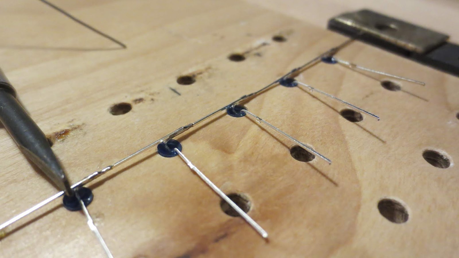

Hint: You might find as I did that LED legs can be attracted with magnetism.  So, you can have a weak magnetic field (e.g., using the magnetized tip of a small screwdriver) hold one LED to another while you're soldering.

Hint: Joining the first two LEDs of each shishkabob is usually the hardest part, because the first LED is likely to rotate around as you're trying to stabilize things for solering.  You might find ways to stabilize the first LED with tape or other mechanisms.  Once you have the first two joined, they stay in the jig, and that prevents further rotational problems.

Hint: A little "overbending" of the cathode might help.  Normally you start by bending the cathode flat against the jig, without touching the prior LED, and then position the leg to touch the prior LED.  If you go beyond flat by a little bit, it helps secure things for soldering.

Hint: The very first LED can have its cathode bent toward you instead of away from you.  The second LED will then bend its cathode away.  As such LEDs 1 and 2 will have a lot of wire overlap, making for better alignment and soldering.  More importantly, it means that you won't have to clip off any excess wire at LED #1's end.

When you're done, you might want to clean up those solder blobs.  I do that by pressing lightly down with a small, flathead screwdriver tip on top of an LED bulb's area, and then briefly wiping the soldering iron tip across the sides of the connection.  Done right, this helps wick solder into the gap between the wires.  The screwdriver helps act as a heat sink, trying to prevent damage to the bulb.

Repeat.  You'll need six of these LED kebabs to form a single LED layer, and you'll be building six layers.

5.  Bend the loops

This step could be done after bending each LED, if you want.
Place each LED (individually before soldering, or each one of the LED kebab) in the hole that has the peg jig (the one where I used a thin screwdriver shaft for the peg).  The anode lead should rest below the peg (i.e., closer to you).  Bend the anode, wrapping it once around the peg to make a complete circle, so the lead goes around the peg and then ends up pointing out to the right again.


Flatten the bent circle by pushing downward on the circle's wire formation (down = towards the plane of the jig).  This helps with overall consistency.


Finish all remaining loops of the kebab.


Clip off the excess wire past each loop.


6.  Straighten some wire.

Unspool a length of the tinned copper wire, but do not remove it from the spool.  Bend the top into a little loop hook, and tighten that into the chuck of a portable drill.  (Since you've made a loop, there will be two parts sticking out -- the bent tip, and the part still connected to the length of wire that leads to the spool.)  Try to make sure the wire that connects to the spool is centered in the drill chuck.

Clamp or step on the spool so it doesn't move.

Spin the drill for about 10 seconds at high speed.  Here, it helps to pinch a section of the wire near the drill chuck tip to reduce overall vibration.  As you spin the wire, you'll see it start to straighten.

The wire may break off near the drill chuck tip due to metal fatigue, and if it doesn't, clip it off at that end.  Then clip off the end near the spool.  You should now have a length of straightened wire.

7.  Build the outer square of the plane

Put two LED kebabs back into the jig.  One should be on one edge of the jig, and the other should be at the opposite edge.  Make sure the wire loops are all facing the same way.

Cut two lengths of your straightened wire.  The piece you cut should be around 6 x 14mm in length (or in general, n x separation distance).  This will provide some overlap that you can clip off later.  Having that overlap makes it easier to place the wire and keep it stable.

Lay each length of the straightened wire to form the other two edges of the square.  The wire can be anywhere you want, but you'll want one of them to stretch from between LED kebab 1's LED #1 and #2 to the same place as kebab 2, and similarly from between kebab 1 LEDs 5 and 6 to the same on kebab 2.

Try to square those up to look good, and solder.  It helps to have markings on the jig to keep things square.


Building this outer square of the plane serves two purposes.  The first is that it establishes some structure.  The wires also act as a common grounding point across all LED kebabs in a plane, and having two provides for some redundancy.

(It would also be doable to have a single grounding wire across all planes, if you want.  It just makes things really wobbly when you do later steps.)

8.  Fill in the rest of the plane

Remove the outer square that you just formed.
Lay down the inner four kebabs in the same orientation as the others had been.

Put the outer square back down atop the four inner kebabs

Solder the grounding wires to the inner shishkabobs.  You should end up with 2x(n-2) more solder points.


Hint: as with an individual kebab, gaps between the ground wire and a kebab can be resolved by a second soldering pass.
- Tin the tip of the soldering iron
- Melt an initial blob connecting the grounding wire to the kebab LED cathode.
- Do the other solder points
- Go back to over the solder points one by one.  Use another heat-conductive device (e.g., a screwdriver) to press the ground wire down atop the LED wire, in case there was some gap there during initial soldering.  Re-melt the solder point while gently pressing down, and then keep the joint stable as the solder cools.
- Avoid hitting the same solder point repeatedly.  That can cause excess heat and melt or kill an LED.  If you have to hit the same place several times, let it cool each time before you try again.

9.  TEST the plane

Set up a power supply.  The ground line should connect to any of the ground wire points -- either to a cathode or to one of the grounding wires.  Make sure you have an inline resistor between the power line and the test probe point, or else you'll fry out LEDs as you test.  (In my set-up, I have a current limiting/clamping bench power supply, so I  keep the voltage to around 3 VDC, and gradually bump the amperage up to a point where it leaks current through.)

10.  Repeat, building the other five planes.


11. Set up the corner columns

This step is a little difficult to get things squared up properly.
The idea here is that you want four columnar wires to stick up from the main board in such a way that they're square -- i.e., orthogonal to the main board.
In order to affix each wire to the main board, you will need to solder each corner wire to the main board, and so at some point you'll need to have the main board inverted (or on its side) to do the soldering.

Here's what i'm thinking for this step:
11a.  Add some felt drawer bumper pads to each corner of the main board (on the copper side, i.e., the "down" side).  This will allow you to poke columnar wires through the main board, and have a consistent amount of wire on the under side.

11b.  Straighten and cut 36 columnar wires of a consistent length.
For me, I had 14mm separations between LEDs.  If we have all six planes at a height of 14mm apart, and we start the first at 14mm, then I'll need at least 84mm of height.  And then I'll need a little more to get through the FR-1 board and out the bottom side for soldering.  However, I'll want it to be a bit longer than that, because I'll need soldering space between the upper layers.  So, I chose to add a few inches to the length.
84mm = about 3.3 inches
I cut mine to 5.5 inches.
I also used 22 gauge wire for these wires.  The holes for the main board were cut at 0.8mm, and 22 gauge wire is about 0.65mm, so the 22 gauge wires should slide through easily.

11c.  Set the board on a flat surface, felt bumpers (copper) side down.

11d.  Insert the four wires that are at the four corners of the cube.  Each should slide through easily and rest its bottom tip on the flat surface below the FR-1 board.  But, because of the slop in drill hole, they will not stand up straight.

11e.  Slide all six LED planes onto the four corner columnar wires.  All the planes should be oriented the same way.  I choose to make all the loops point toward the back, so they're all on the same side as the control headers.  Try to adjust the planes to ensure the topmost plane is level.  (Individual planes might have some warpage to them as a result of soldering.)
In the image above, I have the bottommost layer (layer #1) laid down near the board, and the five upper layers supported by a bridge made of test breadboards and my wooden 14mm spacers.  This is before I realized that having alligator clips would be a better approach.  Instead of the breadboard and spacers, I could have attached four clips, one per corner columnar wire, below layer #2.

11f.  Attach four alligator clips, one for each columnar wire, above the topmost plane.  All we're doing at this point is giving the columnar wires some structure.  Align the columns to try to make sure everything is squared up.

11g. Using care to keep the FR-1 board from slipping off the four columnar wires, invert the whole cube, allowing it to rest upside-down on  your flat surface, held up only by the four columnar wires.

11h.  If possible, use some kind of square object (e.g., books) to keep the whole contraption square.  Bump these up against the sides of the six LED planes.

11i. Apply a bit of solder flux to the holes where the columnar wires are sticking through.  Solder two opposite corners' columnar wires to the FR-1 board.  Don't do the other two yet.

11j.  Check for square.  If either of the wires isn't sticking straight down, orthogonal to the FR-1 plane, then gently melt the solder at that point while adjusting the whole assembly for square.

11k.  Solder down the remaining two corners.

12. Lift the planes
Re-right the assembly (so the copper side is down again).
Undo the alligator clips, and re-attach them at the top of each columnar wire.
Lift all six layers nearly to the top of the columnar wires, so the topmost layer is touching the alligator clips.
Add four more alligator clips just below the raised, bottom-most LED plane.
At the end of this, you should have all six planes elevated above the FR-1 non-copper surface.

13. Lower the first plane
Place 14mm spacers on the FR-1 board perpendicular to the grounding wires (i.e., parallel to each kebab).

Undo the four lower alligator clips.

Lower the first plane, but keep the remaining planes held high, supporting LED plane 2 at each corner.

The first plane should rest its ground wires upon the spacers.

14. Thread remaining columnar wires
At each of the remaining columnar wire points (n x n - 4) slide the wire through its set of LED loop holes, threading from top (layer #6) to bottom (layer #1).  Double-check to make sure you didn't miss any.  Slide the wire down through its proper hole in the FR-1 board.  A set of needlenose pliers can help move the wires through, and it helps if you thread the innermost wires (the ones at the center) first.  Each wire's bottom tip should touch the flat surface under the FR-1 board.


Steps 13 and 14 could be done in reverse order, if you wish.

15.  With layers #2 through #6 raised, solder layer #1 to all columnar wires.

Moving from the centermost columnar wires out, do your soldering, but use the spacers.  Remember that each kebab isn't perfectly formed, and may have some warpage.

Place the spacer below the ground wires at the center, ensure firm contact between the grounding wire and the spacers, and then do the soldering.

Note: the LED loops that were bent earlier allow for some slop in movement.  You might find some are tight, and some are loose, and that's ok.

16.  Test all the LEDs in the layer

This is the point where you should make sure you didn't kill anything while attaching the layer to the columnar wires.  Make sure your power supply is at a safe voltage, and is current-limited (either via power supply settings, or using a resistor that's appropriate, e.g., 220 ohms).  Attach a grounding wire to either ground wire of the plane.  Then, briefly touch the (current-limited) power line to each columnar wire's top end.  One light should light up with each touch.

Repeat the test if you want, to make sure you're not burning out LEDs as you're testing.


17.  Check below the board

With layer #6 secured from above (clips on corner columnar wires above layer #6), invert the entire cube.  The bottom of the board should look something like this, only having the four corner columnar wires affixed at this point:
If you got all the other columnar wires threaded through properly and soldered to the first layer, they should not fall out at this point, and they should be poking through the board as shown.  If any wire falls out, you didn't solder it properly layer #1, so go re-thread it all the way through the board, and try again.

If a wire is affixed to layer 1, but is not poked through the board, you have to fix that, too.  You'll need to de-solder the problematic wire where it joins to layer #1, slide the wire through the board, and re-solder at layer #1.  If the wire is aligned well with the board hole, you may be able to just warm the solder at the joint, slide the columnar wire down and through, and then finish the re-soldering in one motion.

I recommend against soldering all columnar wires to the board at this point.  Later, after the whole cube is soldered up, you may need to adjust things to be level, and it may be that the best way to do that is to de-solder a corner columnar wire and re-solder it.  Doing that with all columnar wires attached to the bottom board (safely) is very, very difficult.  So leave them loose for now, but check at this step to make sure everything looks ok.

This is also a good point to try to adjust your four columnar solder points to avoid shear and torque of the cube.  Do so by finding some other squaring devices to keep the planes aligned to each other, de-solder each corner point from the board, and twist move the board to get the overall cube shape as you want it.

17.  Solder and test each plane in turn

Lower layer #2 down.  That means: release the clips that are holding layer #2 in place, let layer #2 slide down the four corner wires, and then re-clip to keep layers #3 through #6 up high.

Separate layers #1 and #2 using a spacer.  Just as you had used the spacers to keep layer 1 from touching the board, use the same spacers to keep layers #1 and #2 apart.  (Note: in an ideal world, I could use four or eight laser-cut "ladder" spacers, which would have grooves for holding each layer at a known height.  Re-using spacers as I'm saying here runs a slight risk of magnifying error in the spacer heights, making one end of the cube increasingly higher than the other.)

With layer #2 safely in place, solder all columnar wires to the layer loops.

Once all solder points are done, test the entire layer.

If you find a dead LED while testing, it probably means you sat on a loop-column joint too long, and burned the LED out (melted the wire out of its protective covering).  There aren't great options at this point.  If it's on the outside, you stand a chance of replacing and re-attaching an individual LED.  That is doable and takes some patience and dexterity.  If, on the other hand, the burnt LED is somewhere inside the cube, you may have to de-solder everything on that layer, and remove it and all layers above.  Then, you get in the game of re-threading each layer from above.  That, too, is a game of patience

In any case, you don't want to end up with all layers in place, and only then find out that there's a dead LED somewhere below.  It's much easier to fix it before layers higher up are soldered. So be diligent, and test every light for each layer as you build up the cube.

This is a picture of layers #1..#3 in place, with layers #4..#6 still waiting their turns.
(If anyone's wondering, yes, I got some LED strip lights and put them onto my solder filter fan so I could have better lighting while I was soldering more safely.  Nothing too fancy.  It's powered by the same power supply I use for testing my LED cube, so I have to be careful to wind down the voltage every time I'm done using it.)

This is the LED cube after all six layers have been added.  Remember when we measured the columnar wires and allowed for a few extra inches on each one?  While that might seem wasteful, the purpose was to be able to keep layer #6 raised up while layer #5 was being soldered, giving you room to work.  Now with everything attached, there are lots of wires sticking up pretty high above layer #6.

18.  Trim the top, level the board

This is kind of your last good chance to test all LEDs on all layers, so do that.

When you are satisfied that everything is working, you can trim the excess wire off the top of each columnar wire.

Now, you should have a relatively flat top ot the cube.  There will some variance here or there, but it should be pretty flat.

However, it may be that your overall cube is not level with respect to the board.

There are several things that could be happening.
Roll.  If you look at the cube from the side, and the overall layout of the lights looks cube-ish, but it's not level to the board, it's rolling or pitching one way or another.  You'll be able to fix that by inverting the cube, resting it gently on the layer #6 LEDs, and then you can adjust the solder points at the four columnar corners.  Be extremely careful here not to let the board slip upward, and get unhooked from the cube.

Shear.  If you look at your If you have a bit of a parallelogram shape going on, it's really hard to fix.  You have to avoid that at an earlier stage.

Torque.  If you look at the cube from above, and it seems to have a bit of a twist going on, you may be able to bend things gently back into shape, physically twisting the cube into position.  But generally speaking, you should have tried to avoid this at an earlier stage.

Here's my cube with the top trimmed.


19.  Solder to the board

You should now be able to invert the board, and solder all columnar wires to the board copper.  Use a dab of solder flux at each point to get a good connection between the copper plane and the wire.

Clean up any rosin flux at this point.

20.  Attach the grounding wires

There are six wires that you need to connect between the board and the grounding line of each layer.

Set the cube right side up.  It should still be elevated off of your work surface by the felt pads.

You'll do each grounding wire in turn, starting with the innermost board hole connecting to the lowest layer.  Move out one board hole and up one layer as you proceed with doing subsequent layers.

Straighten some wire and cut off chunks that will reach from below the board to the grounding wire.  There are different artistic ways of setting this up.  A simple approach is just to poke the wire through the board hole, having it touch the desk surface beneath.  Then bend it at the point where it meets the board, and lean it over so that it touches the appropriate ground wire.  Solder the wire to the layer's ground wire, and trim any excess.

Another approach is to make an ell shape in the wire.  This takes more careful measurement, but can yield a pleasant appearance.

When all six layers have had their ground wires set up, invert the cube, and solder the ground wires to the board, using rosin flux at each point.

Clean up any rosin flux.

21.  (Optional) Test using board connections


At this point, you should have a nearly functional cube.  You should be able to use normal power supply probes (with proper current limitation), touching ground to a grounding wire solder point on the board, and touching (current-limited) power to each hole where the headers will connect.  Each light should light up in turn.  It's helpful to place the cube (gently) on its side for doing this test, and it also helps to have a mirror so you can see the lights light up.

22.  Solder all headers

For each header row, get the appropriate header pin set, and push it through the proper set of holes.  For this step, I buy 40-row female 0.1"-pitch headers, and I use a saw to cut them to the sizes I need.
 
I also have designed my board so that all power pins are in the same row, but there are some gaps along the way -- places where there's a pin in the header, but no corresponding hole -- so I trim some pins before inserting the component into the holes.


I recommend using solder flux around all the pins before soldering.

Roughly solder one end of the header to the board.  Then, applying light pressure from above, melt that solder point, make sure the header is flush to the board, and then let the solder point solidify.  If you're satisfied with how it looks, solder the opposite end, check for flush, and then solder remaining points.

Similarly solder the grounding wires' header pins.

Clean up any rosin flux.

This is what it looks like with the power headers in place, the ground wires attached, but no ground headers attached yet.  (Steps 20..22 can vary in order.)


23.  Trim excess

You may have excess wire at various points here, particularly at the end of each kebab, and at all poitns below the board.  The ones below the board are safe to trim.  The ones at the end of each kebab may be trimmed, but carefully.  If you built each kebab with the topmost LED cathode pointing away from you, it will have a very weak connection to the next LED's leg.  So before you trim those, double-check that the solder is good, and if you do trim it, try orienting your wire cutters so that they cut "sideways", i.e., the cut goes across both legs at once.

This is the view beneath the board prior to flux cleaning.


24.  You're done!

At this point, you're done with construction.  You may opt to do one more round of testing to make sure all the headers are talking to the board properly.

From this point, it's all about the controlling hardware (e.g., Arduino) and software.


Saturday, December 2, 2017

Arcade game cabinet 1 - ideas and the Midway multicade

Arcade game build/restore

Amidst all the various projects I have in varying states (started, abandoned, nascent), the one I'm now pursuing is building an old school arcade game.

There are so many posts of these things online, it's almost silly for me to think I'm adding any knowledge to the world.  So this is probably going to be more of a log or journal in my travails moreso than a "how to" document.

The game

For starters, there are a number of ways to get games working on a system, some more kosher than others.

Option 1: MAME

The MAME approach requires getting games running on an emulator, and display to a computer screen (via whatever the computer has for video out).  I tried that in full-power computer form and Raspberry Pi form (lower power).

For both approaches, it was useful to get an arcade control board with a USB connection. If you don't do that, you can do some game UI actions using your keyboard, but it's clumsy.

The arcade USB board was a little thing with lots of plugs for 2-pin connectors that would connect to switches (joystick, buttons), and one place where you'd connect the USB dongle to your computer.  Initially, I thought the thing was just acting as a keyboard-type device (i.e., the USB chip on the board would report that it's a keyboard), and you'd map the device's simulated keystrokes to the ones expected by the MAME software.  Instead, it reports itself as an arcade type device.

Upon firing up MAME, the system would recognize the arcade device, and allow you to set up mappings.  It took me a while to figure out that UI, and it's not very forgiving if you make mistakes.  But it was pretty cool, being able to choose an action (e.g., Joystick up) and then just move the joystick to the up position, and that would be recorded in the config file(s)..


But the MAME approach has obvious limitations when it comes to getting actual games.  You have to find ROM images somewhere, and then there would be the gray area around whether possession of those ROMs would entitle you to holding binary images of the games.

For both systems, too, I didn't get to the point of figuring out how to make the computer auto-boot to start up MAME in any particular game.  I'm sure I could have figured it out eventually with the Pi, but I had other ideas.

Option 2: Get an arcade game

The next choice would be to just go out and get an arcade game and fix it up.  As it turns out, there was one for sale nearby and I bought it.  It's a Midway multicade.  An example (in better condition) is here: https://www.youtube.com/watch?v=pYRc3314WYc.  After purchasing it and reading up on it (perhaps it's better to do that in the opposite order), I found that it had been sold historically via real brick & mortar stores, increasing my confidence in the validity of the game licensing.

One discussion about this kind of game and cabinet, and moreover its shortcomings, is here: https://forums.arcade-museum.com/showthread.php?t=73341

And as that discussion outlines, it's cheap.  It's not a full stand-up arcade game, being only about 5' tall, and it has a cramped, small control panel.  Both video and audio came from a 13" CRT TV.

While I was disappointed in my purchase, it felt good to have properly licensed games (or at least that's what I think they are).

Option 3: JAMMA

The next area I would look into was JAMMA boards.  There are numerous kinds of JAMMA boards out there, and they usually have dozens or even hundreds of games.  Each conforms to a pretty well established pinout standard, so you just get one of those boards, attach the board (56 pins, 28 per side) to a "harness", and then connect a spaghetti set of wires to various things.

The Midway multi game

Cabinet

Here's a picture of the Midway system.

As you can see, the cabinet is in poor condition.  Most of the front artwork was faded or water-damaged.  Because it was in poor shape when I got it, I stripped more of it off so I could disassemble it (both to take a peek inside, and to transport it without breaking my back).  Eventually, stripping off the artwork also gave me access to the game cartridge.

The cabinet for this is odd and fairly cheap.  It appears to be 1/2" MDF for the main walls, and thinner MDF for the back.  Mine has some water damage at the back base.

What's also funny about the cabinet is that it can be disassembled in thirds.  A regular arcade game's cabinet walls (left and right) would be a single piece of 3/4" MDF.  For this one, each wall is comprised of three pieces of 1/2" MDF, and there are interior supports and junctions that guide one third to sit atop another.  I can take off the back panel, and then undo a few bolts, and the whole top third can come off.  There are no electronics in the top (whereas a real cabinet would have a power switch, lighting wires, and maybe speakers).

Control panel

The control panel looks like this:
It provides a fairly cramped two-player capability with six buttons per player, plus player 1 and player 2 start buttons.  (There are no coin slots, and there are no service or test switches.)  While I envisioned creating a single-joystick CP for building my own game, the ability to play Robotron (need two joysticks for one player) or Joust or Rampage (more fun playing with a friend) argued well for this kind of CP functionality.

The joysticks themselves are cheap, but functional.  The buttons feel small, even though physically they compare well with standard arcade buttons.  More importantly, they have too much spring resistance.

There are some games where the button layout really makes a difference.  For example, Stargate and Defender have meaningfully restrictive joystick movement (vertical only), and a Reverse button is placed near the joystick.  Then, the Smart Bomb and Hyperspace buttons are separated farther out.

What I'm striving for is a CP that can be customized or swapped based on the game in play.  I'd rather have a layout that is faithful to each original game, rather than a generic, multibutton panel.

The CP itself also is just a plastic box, and you can hear it creak and groan as you play.  A more standard old school CP might have a metal plate supporting things, but most cabinet construction uses 3/4" MDF or plywood, routed out so that the controls fit and the joystick doesn't sink too much.

The monitor (and audio)

The monitor is a little 13" TV.  It has front-panel push-button volume controls.  The two little red buttons on the image above (the buttons above the Player 1 Start button) are just extensions of the actual monitor controls.
The audio for the game comes from the TV's own speakers.  As such, the game system simply has to emit audio left and right signals, and a TV video line.

Internal electronics

Power is switched on using a rocker switch on the side.  There's a hole cut out of the wall that provides access to the switch.  The switch turns on a box that provides power to both the TV (pass-through 110VAC) and the game board (6VDC).

The game board is enclosed in a cartridge, and the cartridge plugs into a holder.  I assume this cartridge-style architecture was done for common structure in manufacturing, so they could release some other multicade with other games with just a change of cartridge and outer labeling..
The cartridge plugged in through the front.

Cartridge removed


The cartridge holder has a locking mechanism (screwed in clip that prevents removal of the cartridge from the front).  The locking clip is only accessible from inside the cabinet via the rear.

This is what the back of the cartridge looks like:
Cartridge rear - allows for push-in connection
Cartridge rear close-up. 18x2=36-pin finger board connection, plus audio left, right, and video out.
The cartridge pins have to account for these things:
Six buttons per player
Four joystick positions per player
One start button per player
Grounding wires
6VDC and ground in
An LED light pin that indicates that the power is on.

That adds up to 24 pins.  (As you can see on the solder-side close-up, there are four pins labeled "N.A.")

Here's what the cartridge looks like on the inside:
Solder side (cartridge bottom), view 1

Solder side (cartridge bottom), view 2, close-up

Component side (cartridge top)

The board designers were kind enough to provide text descriptions on each pin on each side, so it's clear in the picutres which pins serve which purpose.  Thank you, board designers!  (Also, thanks to the cartridge designers who allowed me access to this via four Philips screws.  None of the "let's make this sleek and make people pry it open" mentality here.)  The audio outputs are labeled, too, so I can know which side is left vs. right.

The rear of the cartridge holder has these things:
A ribbon cable that connects to the control panel, power input, and LED.  (Need pictures of ribbon that connects to the cartridge holder, and the ribbon end that connects to the control panel.)
RCA connectors for red (right audio), white (left audio), and yellow (video)

I won't go into the ugly details of the inner wiring of the joysticks and buttons.  That stuff should be pretty obvious to anyone who is working with Sanwa joysticks and Happ buttons.

As far as I know, all remaining wiring is just plain switches and connectors.  For example, the power LED is just that -- an LED with no other inline resistors, etc.  All electronic componentry is kept on the cartridge board.

To be added:
- Ribbon end connectors
- Maybe: internals of the cabinet, and how things are made (for better or worse).

Conversion

For a better arcade game experience, I want to retain the guts of this cabinet, but use a real, solid cabinet and controls.  The games do play nicely, though the video output board probably is of limited resolution.

The only pieces worth keeping are:
- The power supply (to feed the 6V input that it is used to getting)
- The cartridge
- The cartridge holder and ribbon cables.

What I wouldn't find useful:
- The control board, all buttons, and joysticks
- The 13" TV
- The cabinet walls and shelves and artwork, and other cabinet parts (hinges, fasteners were of poor quality).

To connect the cartridge to a new system, I have a few options.  I could get a "finger board" like this
http://www.twistedquarter.com/index.php?main_page=popup_image&pID=1715
or
https://www.mikesarcade.com/cgi-bin/store.pl?sku=JAMMATYPE2
and then chop it down to 18 pins.  Then, I'd wire directly from it to something more standard (JAMMA).

The other way to go would be to map the ribbon output of the cartridge holder.
Yet another option would be to cut the wires that connect to the existing controller, label each wire, and solder those to a JAMMA finger board.  While that has multiple connectors involved, each of which could wiggle loose, it probably is the least costly solution.  I couldn't preserve all the button functionality of the original, since JAMMA only supports up to 4 "fire" buttons per player, not 6, so some wires would end up hanging loose.

Any way I play it, I'll need to find some solution for mapping the Red/White/Yellow RCA outputs of the cartridge to whatever JAMMA needs or whatever the monitor needs.  I am thinking I'll circumvent the standard JAMMA output, and use VGA instead, but that may involve crafting a VGA switch as well.  And yet another possibility there is that the monitor I choose might support RCA and VGA inputs, and I could just click to a different monitor input choice.

Audio

I'm realizing that there's another issue in conversion of audio.  The cartridge is probably emitting line level audio output in stereo.  But JAMMA outputs amplified signal (speaker-ready), and in most cases emits mono (monaural) output.

I had thought of building a stereo-to-mono passive bridge (just a couple of resistors connected to each R and W signal, then joined to hit a single mono signal) but maybe that's going in the wrong direction.  Instead, maybe I should make the cabinet with stereo speakers, and have a switch that lets me choose which way to set up audio.  When in JAMMA mode, it would split the amplified mono to stereo (but can't just be a parallel circuit due to impedance drop that that would cause), and when in Midway mode it'd go through an amplifier to the stereo speakers.  What should I do?

Next up: the Midway Mortal Kombat II cabinet rebuild approach.

Sunday, January 17, 2016

"Perpetual motion" / "Perpetuum mobile" laser cutting

"Perpetual motion" / "Perpetuum mobile" laser cutting


I was able to put together -- rather surprisingly quickly -- a Java program that used all the computations in my previous post.  The main design points were:
- use double floating point precision
- use variables for all things I choose (inner radius, "D" length) and all things that could vary physically.
- allow for kerf compensation, given the laser cutter could eat more material than I expect
- allow for variable material thickness
- generate SVG as the output format
- push the output to an output stream, which I later converted to dump data into a known file

Initially, just to check my computations, I'd drawn the pictures on graph paper and used a rule to measure the actual lengths.  I then used Excel to compute everything, and compared against the physical measurements.  Once I was confident in the equations, I transferred them to Java program form.


The main iteration cycle I'd go through would be
- edit the program
- run the program
- load the output SVG file into Firefox, where it would render the results
- iterate

Sometimes, I'd check the output in pure text format using a simple text editor like vim.  That also would allow me to edit some entries to see if different forms of SVG would be better than others.

Initial SVG output

My initial output was very much brute force, generating <polyline> tags with (x,y) pairs in the attributes of the polyline, and I generated all data that way.  Also initially I just wanted the D and qhyp lines.

SVG is a very simple format to use for this.  I had used SVG before, but found it useful to just read up on the info at
http://www.w3schools.com/svg/
From there, I jumped into examples of an SVG Polyline.

Roughly speaking, the initial output looked like this:
<svg>
<polyline points="x0,y0 x1,y1 x2,y2 x3,y3...." style="fill:none;stroke:black;stroke-width:3" />
...
</svg>

The code then would iterate so it was something like this:

... Set the main R, D, and theta variables
... Compute all the other things like A, H, XDL, XDR, Q, qhyp

print "<svg>"
for (int i=0; i<nSegments; i++) {
  angle = theta * i;
  convert angle to radians
  rotate (R,0) through angle using a normal rotation matrix
  rotate (XDL,H) through angle
  print the polyline with points="R,0 XDL,H" as appropriate each time.
}

... Similarly, draw the points from XDL,H to XDL',H' to build the edge walls.
print "</svg>"

The need to transform and scale

After generating the initial output, I found a few things were problematic.  First, the output wasn't visible unless I provide width and height attributes in the initial <svg> tag.  Also, if those values weren't large enough, the drawing would be clipped and the overall window wouldn't let me scroll to see it all.

Second, the output wasn't the right size for me to look at it properly.

I changed the code to generate output like this:
<svg width="800" height="600">
<g transform="translate(400,300)">
<g transform="scale(2.5,2.5)">
... do what I did earlier
</g>
</g>
</svg>

The origin in SVG rendered on screen would be at the top, left corner of the canvas, and Y increases as units move down the screen.  For me, the inverted Y axis didn't make a difference, because mirroring a cut on the laser cutter could be achieved by flipping my material over and running the same cut.  If it matters to you, then you could negate the y scale value, and translate further.

Note that the transformations are applied in inside-out order, so in the example above the scaling happens first, then the translation.

Simplifying the coding using transformations

Once I knew there were SVG native transformation operations, it meant that I wouldn't have to compute the point rotations myself.  Before the code was of the form

for i in 0..(360/theta)-1
{
  compute the x,y points at rotation angle "i*theta"
  print the appropriate svg to draw a line
}

Now the code is

compute the x,y points once at rotation angle 0
for i in 0..(360/theta)-1
{

  print ("<g transform=\"rotate(" + (i*theta) + ")\">");
  draw the shape as if it were at rotation angle zero
  print ("</g>")
}

The need not to scale

Fairly quickly, I found that the scaling operation I was doing would scale everything, including the width of lines.  Anisomorphic scaling (i.e., x scale is not the same as y scale), coupled with the scaling of line widths, resulted in having a unit square turn into a rectangle, but that rectangle would have thick edges on the short sides, and thinner edges on the long sides.

In laser cutting at the TechShop, a hairline edge width is used for cutting, but thick edge widths imply rastering (etching), so having non-uniform edges due to scaling was problematic.

Also, having scaling meant that I would have to reverse the scale computation for elements where I had a known, required final value, such as the width of a hairline.

Once I knew that out, I took out the <g transform="scale(x,y)"> operations.  Instead, I'd have to generate the SVG output using full size coordinates.

File format versions

Once I had a basic drawing in place, I took it to the TechShop and loaded it up in CorelDraw.

In the past, I've had problems loading SVG into CorelDraw.  The primary problem appears to be around curves or splines that are closed, where earlier versions of CorelDraw would not handle them properly, and would send closing vectors off to Never Never Land.

For this SVG, however, I was drawing very simple primitives, and I could load it directly in.

I did find that some computers had different versions of CorelDraw installed, and if I would load .svg, convert to .cdr, and save, it might not be readable in an earlier software installation version (CorelDraw 5 can't read CorelDraw 7 output).  To get around that, while I still hadn't ironed out my .svg output, I could export from CorelDraw 7 in .pdf, and load that into CorelDraw 5.

Pixels? Points?  What are SVG units?

There were two things I wanted to check when loading my SVG file into CorelDraw.  The first problem was units.  Since my SVG file was output with simple commands like <polyline points="100,200 200,200">, it wasn't clear exactly how those would measure out to become physical values in real world units.

A second problem that arose, still related to units, was that the concept of a "hairline" line width is what determines whether or not the Epilog laser cutter will cut as vectors, or etch as rastering.  CorelDraw doesn't explicitly show the line width in millimeters when it's set to "hairline".

My initial path here was to take a value like "100" SVG units, and compare against what was being shown in CorelDraw in millimeters.  I'd generate the SVG and load the file into Corel Draw.  Then, I'd set the ruler units (Ruler Settings option menu, then set units to millimeters) and click on an object to see how big it was.

Since the code was generating lines at angles, I had to find a generated line or rectangle that was at a multiple of 90 degrees.  Once I knew the SVG value and its corresponding CorelDraw millimeters value, I got what I thought was an SVG-to-mm ratio.  As it turns out, though, that was a mistake.  It seems that default units are "pixels", and the ratio might vary from one computer to the next.  I'm not sure, but it's definitely better to use real units and not rely on "pixels".

I also looked up the definition of "hairline" online, and it ends up being 0.00762 cm or 0.0762mm.  So, with my errant unit conversion ratio, I generated some SVG values for the "stroke-width" attribute, loaded in CorelDraw, saw "hairline" in the interface, and was happy but inaccurate.

D board, Q boards, tabs, intersections

The walls could be plain, rectangular boards, glued down to the base. But in laser cutting tradition, I chose to cut tabs and slots for them to plug into.

Here's the first sketch I had for what I'd want the boards to look like.  It's not really correct, because each D wall hits the next D wall.  But it shows the kinds of tabs to think about.

The D boards would have one tab sticking into the base.  I would choose where that tab would go, and opted to put it some percentage distance down the length of D.  I arbitrarily chose the tab length to be 20% the size of D itself, and messed around with the placement percentage to get it to hit somewhere along the RestD section of D (not along nor intersecting Base).

At the top of D, where it hits the outer edge, the board actually intersects with two Q boards at the same time.  The drawing under the Kerf heading below shows what they'd be shaped like.  The thought was to create each board in this way:
- The tabs would be 1/6th of the wall height.  Each board would have two tabs where needed.
- The D board outer tabs would be the "middle" tabs.
- One end of Q would have the "upper" tabs, and the other end would have the "lower" tabs.

This is a top-down sketch of the D boards hitting each other (labeled "Intersection point"), and at the outer edge, a D board hitting two Q boards.

Kerf

Since I'd be cutting tabs and slots, I might have to compensate for kerf, which basically meant I'd have to cut less from the slots, and more around the tabs.  The laser cutter burns away a small amount of material, much like a table saw would cut about the width of a saw blade.  While the laser is much more precise, the amount of material removed is not zero.

This is a drawing of what the kerf compensation cut lines would look like.
The red lines show what the actual object would look like, and black lines indicate where the laser cuts would be.  Material between black and red represent the kerf.

The top part really should just be "MThick" (material thickness), not "MThick + 1/2K".  The idea here is that I can draw these parts with simple x,y changes, so the code would say something like this:
print the polyline tag;
print x + "," + y + " ";
y += 2*T;
print x + "," + y + " ";
x += materialThickness;
print x + "," + y + " ";
etc.
print close polyline tag;

The bearing

At the center of the base circle, I wanted to press in a regular inline skate bearing.  I had several laying around still from the JGRO project that started, but stalled.  The outer diameter of one measured at 22.01mm, quite accurate for what the internet declared to be 22mm OD.

To add the circle at the middle of my drawing, I wanted to cut a 22mm circle, minus half kerf on both sides.  That would mean having a circle whose diameter was 22mm minus 1 kerf (radius is 11mm - half kerf).  In SVG, that would come out looking like this:
<g transform="translate(x,y)">
<circle x="somex" y="somey" r="someradius" style="fill:none;stroke:black;stroke-width:3" />

</g>

and, since I was treating the whole page origin as the center of the circle, I could use the default x,y values and just draw it like this:

<g transform="translate(x,y)">
<circle r="someradius" style="fill:none;stroke:black;stroke-width:3" />

</g>

Test cuts

Concerned about the fit of the tabs to each other, tab fit within slots, and bearing fit within circle, I did some test cuts of each.

The first test cuts are the five figures on the left side of the board.

For my "D board" test cuts, since I was dealing with a smaller piece of scrap and didn't want to waste material, I used CorelDraw to trim off a few nodes, and made two of them.

The first problem, and pretty much a showstopper for everything, was that the bearing circle came out at 21mm, far too small for the bearing to press in.  I wasn't sure if the error was caused by an incorrect kerf setting, or because of the SVG-to-mm conversion ratio I was using.

I also took the two D boards, and put their tabs against each other.  If cut correctly, they would have a smooth surface going across, but they didn't.  Instead, there was a bump up, suggesting the resulting tabs were ending up being too large.  That meant my kerf compensation value was too large (I'm on the outer edge, so cutting too far away from where I want the resulting edge to be), or my units were wrong, or both.

I then ran a second test cut with a bunch of circles of varying diameter.  Once I figured out the "right" size of a circle for my bearing, I could use that as my target for the generated SVG.  Here, CorelDraw provided a nice accelerator.

To draw circles in CorelDraw, you can choose the ellipse tool, and hold Shift while dragging to ensure the result is circular.  Then, you can select your circle (click on its edge) and hit ctrl+D to duplicate the circle.  After that, drag the new circle to a new location, and CorelDraw will remember the offset.  From there, you just hit ctrl+D again and again, and each newly duplicated circle will be offset the way you chose.

What I didn't know but learned in this exercise is that CorelDraw also will auto-adjust dimensions when you hit ctrl+D.  So what I did was:
- create circle
- using the dimensions pane, change width to 22mm and height to 22mm.
- select the circle
- hit ctrl+D to duplicate
- move the new circle to a nearby, non-overlapping location to the right of the original
- using the dimensions pane, change size to 21.95mm
- hit ctrl+D again and again
In the end, I had six circles ranging from 22mm to 21.75mm.  I just cut them all out, and tried each one with the bearing to see which woud fit best.
Because I put them too close to each other, I did a third test cut with 21.85mm and 21.8mm diameters, but with a lot of material between.  I still came out with 21.85mm being a nice, snug fit.

For the bearing hole, I also added two additional washer-style circles to be cut out.  Those were just in case the material was so thin that the bearing wouldn't have enough to grab onto.  With thin material, I'd just stack the washers over and concentric with the bearing hole, and that would provide enough thickness for a good seating of the bearing.

Reconsidering kerf compensation

The bearing circle diameter value of 21.85mm for a 22mm physical object suggested that the kerf value was actually 0.15mm, and that would translate to a very small fraction of an inch (0.005905512 inches)..  I had been assuming a 1/32" kerf, though, which would be 0.03125, about five times as large.

Left confused by the 5x factor, I just gave up on the kerf computation completely.  I dropped the kerf variable down to zero, and re-cut some D and Q boards.  After doing that, they slotted into each other quite nicely, with no noticeable step created at the top or bottom when joining the three boards together.

I also tried pushing the zero-kerf boards into the rebuilt-with-zero-kerf slots, and they fit somewhat snugly, so I went with it.

That left me just trying to figure out how to make sure my circle would come out as 21.85mm, because I still didn't have real physical units expressed in my .svg output.

SVG real world coordinates, and style sheets

So how do you figure out how to tell CorelDraw how to draw things in real world coordinates?

Turns out it's pretty easy.  But here's how I backed into it.

I started by creating a brand new file in CorelDraw, and saving it as SVG.  The file that was created showed me a few things.

First, the unit type is declared in the opening <svg> statement, where the width and height are stated.  So at the opening of my file, I really want something like this:
<svg width="800mm" height="600mm">


From that point onward, all unit measurements are assumed to be in that unit type, and they are not declared with their own unit type.

So, to get the bearing circle, I would just have to say this after having set up the millimeter unit type at the start of the file in the <svg> tag:
<circle r="21.85" style="fill:none;stroke:black;stroke-width:3" />


Even the viewBox declaration within the same <svg> tag is stated without a unit type.

I also noticed that the CorelDraw SVG output file made its XML format clear, and made use of stylesheets.  The starting portion looks something like this:
<?xml version="1.0" encoding="UTF-8"?>
<!DOCTYPE svg PUBLIC "-//W3C//DTD SVG 1.1//EN" "http://www.w3.org/Graphics/SVG/1.1/DTD/svg11.dtd">
<svg xmlns="http://www.w3.org/2000/svg" xml:space="preserve"  width="610mm" height="457mm" style="shape-rendering:geometricPrecision; text-rendering:geometricPrecision; image-rendering:optimizeQuality; fill-rule:evenodd; clip-rule:evenodd"
viewBox="0 0 610 457"

xmlns:xlink="http://www.w3.org/1999/xlink">
<defs>
<style type="text/css">
<![CDATA[
.str0 {stroke:black;stroke-width:0.0762}
.str3 {stroke:black;stroke-width:1}
.strred {stroke:red;stroke-width:0.1}
.strnocutblue {stroke:blue;stroke-width:1}
.fil0 {fill:none}
]]>
</style>
</defs>


This made it so that I could declare my hairline stroke width once, and refer to it later using a declaration like this:
<circle r="21.85" class="fil0 str0" />

Some decorative swirls

To get a more interesting center, and also leave the base with less mass, I wanted some sun rays radiating out from the center.  I tried some simple crescents at first, but they weren't very interesting, and plain sine curves would cut across each other at the 180 degree point.

Fortunately, MY was home from college and able to whip up a quick formula.
<insert formula here>

Full rendering

I adjusted the code to use stylesheets and millimeter units, and re-ran the code.  I left some areas of the code such that I'd have to change them before each run, particularly the choices of whether to render the base, and/or the D boards, and/or the Q boards.  This is a drawing of the D boards and the base.  (Apologies to anyone with contrast vision problems, but the hairline stroke-width makes things very faint.)


I then took the output to Corel Draw, created a new Broad Sheet document, and copied the objects from SVG into the new page.  The material width and height sometimes wasn't exactly 24"x18", depending on what scraps I had, so it was important to lay the objects out according to actual dimensions.

I also duplicated the bearing washers, and had to manually duplicate the inner circle, and used Corel Draw's alignment functions to keep things centered up for them.

The edited Broad Sheet in Corel Draw 5 looked like this:
 I cut that on 5mm ply, and that's when I ran into the tab collision problem.  More on that later.