Thursday, September 29, 2022

DJ Hero teardown


I was looking for something that could act as a rotating platter for clay sculpting, and came across a DJHero at the thrift store.  Mine is missing the adjacent gadget that is has slide controls.


There are interesting videos online that show how one could be used, but I didn't think they went into enough detail about the inner electronics, so here we go.

On the side that has the data port, there is the port itself, which contains 4 contact points inside, and a hole to its left, which houses a momentary switch.  That switch can be used to identify the device on I2C, so two of these can be on the same I2C bus, as long as they have different switch settings (depressed vs. not).

Overall structure

There are several layers to the device, and I take them apart from the bottom up.  Viewed from the top down, you have

1.  the spinning platter top (exposed layer, where you have buttons)

2. the spinning platter underside (holds the button PCB and optical encoder

3. the middle layer honecomb (supports the spinning platter and has a hole that lets the encoder stick through)

4. the middle layer underside (nothing too special)

5. the lower layer top (all those little teeth!)

6. the lower layer underside (another honeycomb-type support layer)

7. the base top and bottom

Once you remove all the screws, the base bottom can be removed from the base top.  There aren't any annoying plastic clips holding things together.

Base top/bottom

On the underside of the DJHero, which is the underside of the "base bottom", you find four circular feet, each held in place by a T-10 "star"-type screw.  Then, there are five more T-10 screws in the middle, and two T-9 screws closest to the data port.

With the bottom removed from the top, you can see the wires connecting the data port and switch, and all those send wires into the next layer.

The bottom of the DJ Hero has a sliding switch.  It's a physical thing that slides plastic into place so that it locks the side gadget to the DJ Hero.  That can be removed with a Philips screwdriver.  Don't lose the spring.  Also, those parts aren't really necessary, so if you want to route some wires through a hole somewhere, you could just take out the plastic bits and feed the wires through there.

It's a good idea here to unscrew the circuit boards.  You might have to break off some aged glue in order to do this.  It's just a matter of removing the plastic bits, and then removing two screws for each board.  The switch PCB has smaller screws.   If you don't remove the PCBs now, you might have too much tension in the wires as you try to get the other layes apart.

I should mention at this point that any further disassembly isn't really necessary.  In fact, getting to this level may not really be necessary.  It can be useful opening up this first layer (base top/bottom) in order to tap into the wires, or replace the switch mechanism (e.g., with a real SPST switch).  In short, you can stop here, or even stop before opening up the base. 

If you do go past this point, be very careful not to break off the little teeth seen in the next layer.  Don't say I didn't warn you.

Now, going to the combined lower+middle+top layers, remove the four Philips screws around the center.  That will let you separate the lower layer from the middle+top layers.


The lower layer

Be very careful here.  This layer has a ring of plastic teeth. The photo below shows the middle layer removed from the lower layer, and the middle layer is flipped upside-down.


Here are the little plastic teeth.  They serve as photo interrupters as part of a quadrature encoder-type mechanism.


After a few more Philips screws, you can remove the middle layer from the top platter.

The middle layer

This is what the innards of the middle layer top, and the platter underside look like:


 Note how there's a hole in the middle layer.  That's where the quadrature encoder sticks through (from the platter layer) and "reads" the light pulses formed by the ring of plastic teeth.

The wiring simply feeds through this layer up to the control board that's housed on the underside of the platter.

This is a closer view of the encoder board.  The white ribbon cable connects to the button PCB.


This is a view of what's happening on the other side of the button PCB.  It's just three contact-type (graphite paint-type) switches, just like in many keyboards, and a common ground (the red stripe).

This is what's going on on the opposite side of the encoder PCB.

The buttons connect to pins labeled P1, P2, P3, and G (ground).

The wires from the base connect as G, ID, C, D, G, and V.

By wire color, and based on other documents online, they correspond to

G = blue

ID = white = identifier

C = green = I2C clock, aka SCL

D = yellow = I2C data, aka SDA

G = black = ground

V = red = Vdd, 3.3v

The SCL and SDA lines appear to have 1k series resistors, which kind of suggests tolerance to 5v.  But the examples I've seen on other pages suggest using 3.3v works ok.

The onboard chip is labeled HA2003 | I/SS021 | 0933GHE.  I'm guessing its something aking to a PIC16.  All it has to do, I think is count quadrature events, light the quadrature's LED, do I2C communications, and handle button clicks.

The blue and white lines are interesting.  Blue is actually hardwired to ground way back at the momentary switch PCB.  When the momentary switch is pushed, white is connected to blue, meaning it's brought low.  Therefore, I assume ID is biased high.

Hooking in

I rebuilt things back to the point where I just have the base top and bottom apart, and the PCBs are removed.

This is what the back side of the data port PCB.  It's just direct wiring: green, red, black, and yellow wires hooked to connector pins.  


The ground line (black) hooks over to the switch PCB.  There, it's joined to blue wire directly.  The white wire comes off the switch, and gets joined to ground when the switch is depressed.


At this point, I had a few options for getting to the data signals.  One would be to disconnect the existing wires and port, butt-weld some wires, and feed them through a hole.   Another would be to solder to the same pads as the data port PCB itself, but that's not great, because they're already surface-soldered (which means attempting to solder there probably would cause the existing wires to pop off).

What I opted to do instead is make my own little board to use the actual data port.

The data port is just the right size for a double-side board to slot in.  There are two connection points on each side.  It's about 7mm wide.  With the device right-side-up, the inside port pins connect as:

yellow black

green red

I started down the path of Fusion 360'ing a board design, but then just decided to make it by hand.  (It's surprisingly hard to just draw some vectors and say "mill on or inside or outside the line" in F360.  It's way easier in VCarve.)  

I band sawed a 7mm-wide strip, and then sanded the edges and did a test fit for insert.  That worked great, and you could see visible scribe lines where the pins touched copper.

I then cut it to around 15mm length.

I scored a line down the center of the board (very carefully) with a razor, and tested to make sure the sides were not longer in contact.

Then, it was just a matter of a Q tip, dabbing on a bit of solder flux, tinning the pads, and soldering wires.  Along the way, I kept continuity-testing to make sure it was safe.


By the time it's all together again, and because there's no "keying" of the board, it's easy to get it upside-down, so I was careful to continuity-test the dongle's wires against the internal wires prior to reassembly.

Here's what it looks like when the patient's in post-op.


and zoomed in so you can see color coding

A side note re: the underside feet.  Note that they're "keyed".  There's a little nub in the base, and there's a corresponding slot in each foot.  Make sure they're aligned before screwing things back on.


What's next

Now that I have the breakout board, I have to decide on a programming platform.  I'm used to Arduino, but it runs I2C at 5v, so I'll need a bidirectional 5v/3.3v level shifter to get that working safely.  I may instead do this using Raspberry Pi.

I'll probably put a glob of hot glue onto the breakout board to make sure the wires stay isolated and solid.

Then, I'll do it all again, because I found a second DJ Hero at another thrift store!  Yay.

What that means, then, is that I can move from there to replicating the DJ Hero Etch-a-sketch that someone else did.  Or, make a wheelchair-type HID.

The other thing I want to do -- and part of the initial impetus for getting this device -- will be to use the DJ Hero as part of a 3D scanner.  I could use a vertical line laser alongside it, and use the encoder readings to know the rotation position.


Thursday, September 8, 2022

Roomba 655 DIY virtual wall

 I had the good fortune to get a Roomba 655 from thrifting the other day.  Along with it, I got two Roomba bases and a Goovi F007 base, just in case I might find it useful.  I gave everything thorough cleaning and then started into the electronics.

Putting the Roomba onto the base, I would see it light up to charge, and then immediately turn off.  This is typical of fully discharged, rechargeable battery packs that no longer have (or can sustain) a minimum charge.  The Roomba bases appeared to be generating a clean 3+ VDC charge, so they looked ok.

I removed the underside panel per documentation, and found the power pack..  Sure enough, there wasn't any power coming from it.  I don't understand why the power packs have four contact points on the bottom.  One clearly seemed to be a direct connection to GND (based on ohming out the lines between the battery pads and the charger connection points), but the purpose of the other three wasn't clear.

I was hoping to find some instructions for refreshing a pack outside of the machine using a NiMh charger, but there wasn't one on the web.  So, I ended up ordering a $20 pack online.  It arrived, and I put it in, and charged it up.  With just that, the Roomba worked!

My next step was to build a virtual wall.  There are multiple pages out there, but they seem to root to https://github.com/MKme/Roomba and the YouTube video linked from there.

The very basic idea of this: use the IRremote library for an Arduino, run it at 38 kHz, and pulse one for a second, and then off for a second.  That's all.  You get an infrared LED, which can be pulled from most any remote (these show up regularly in the thrifting bins for cheap).  The anode connects to 5v and the cathode (the side with the visibly larger metal inside the LED) goes through a 110- or 220-ohm resistor to the IRremote output pin.

I verified I had working components by connecting the IR LED with 5v - anode - LED - cathode - resistor - GND, and then looked at the LED through my phone camera.  It would show up pink-ish there when on.  That way, I knew I had the orientation correct, and that the LED wasn't burnt out.

Attempt 1

I tried setting up the sketch for an Arduino Pro Micro, and connected to pin 3 as defined.  After wiring it up, I got no light from the LED.  I read some other articles indicating there were issues with the IRremote library and the Pro Micro (32U4).

Attempt 2

I then tried the same sketch using an Arduino Mega 2560.  Again, no luck.  I read one article saying that the Mega 2560 uses pin 9, and if I were to just pinMode(9,OUTPUT) and digitalWrite(9, LOW), it would work.  Uh, no.

For both Attempts 1 and 2, there were pages suggesting making modifications to the IRremote library directly.  I looked into that, and found the lines they were suggesting to modify weren't even in the library any more.

Somewhere in this, too, I saw an example referring to "IrSender" as a known object instance or there were class-level methods associated to it, whereas the original MKme code used Irsend.

At this point, I realized I might be working off of the wrong library version.

Attempt 3 (success)

For my third attempt, I went to a plain Arduino Uno.  It turns out I got one from thrifting.  It was within a Thames & Kosmos electronics kit.  Nice build.  The Uno is buried inside of a handheld gamepad-type thing, and has its own rechargeable battery under the board.  The one I got had a faulty roller switch thing, but the Uno worked.

I first got rid of the old IRremote library that was at

$ARDUINO_HOME/libraries/IRremote

Next, I downloaded the IRremote library version 3.9.0.  I installed it as

$ARDUINO_HOME/libraries/IRremote-3.9.0/{examples, pictures, src, etc.}

Then, I looked at the example

$ARDUINO_HOME/libraries/IRremote-3.9.0/examples/SendDemo/

In that folder you'll find  

PinDefinitionsAndMore.h

and

SendDemo.ino

The sketch first includes the .h file before including <IRremote.hpp>.  Then, it does things based on the pin definitions within setup().  I didn't really care about what it was doing in loop(), since I knew I'd be replacing that.

So, I created my own sketch, vwall2.ino.  As normal, once I saved it, it went into $ARDUINO_HOME/vwall2/.

I copied the example's PinDefinitionsAndMore.h into that folder.

Then the sketch basically was:

#include PinDefinitionsAndMore.h

#include <IRremote.hpp>

Duplicate (verbatim, I think), what's in setup().  Some of that stuff you don't necessarily need, but it didn't hurt to have it.  And, the diagnostic stuff printed to the Serial Monitor was interesting.

Then for the loop(), I did this:

void loop()
{
  //These values should work for pre i models of roomba
  // See timeline at https://en.wikipedia.org/wiki/Roomba
  IrSender.mark(1000);
  IrSender.space(1000);
 
  //For "i" models (i3, i7 etc) use the following
//  irsend.mark(500);
//  irsend.space(7500);
 
}

So, basically, the loop is the same as MKme/Roomba's, but using IrSender.

Also, I googled the Roomba model timelines and found that the 655 preceded the "i" series, so I used the 1000 / 1000 timings.

With that sketch, the default output on an Arduino Uno is pin 3, and I got about 1.1 VDC by voltmeter, and observed the IR LED showing pink through the camera lens.

Physical build

I grabbed a chunk of 30-hole perfboard, and soldered things up.  At one end, I made a 5-pin edge connector with part of an old wire-wrap header.  I bent the pins (using another chunk of perfboard for spacing) so that the pins would end up parallel to the board.


The intent was to put the board in where the pins say 5v, reset, 3.3v, Aref, and 5v.  I chose to use 5 pins for the edge connection for stability -- but of course if you do the same, be sure to make sure you don't solder-bridge any of those pins.  The circuit only touches one 5v pin, and since that appears at either end, it makes it so that I could mount the board either way.  I like having it so that the board is on the inside of the headers, so I'm using the 5v pin that's closer to Aref.

Kosmoduino board.  Red = either 5v point.  Blue = used for support.  Pink = IR LED signal


The 5v pin then wires up to the top of the board, and connects to the anode.  The cathode side connects to the 110 ohm resistor (in the picture I have two 220 ohm resistors in parallel).  From there, I just soldered to a patch wire, so it lets me plug the other end of the patch wire to pin 3 on the Uno.  It's not as elegant as bulding a real Arduino Uno shield, but having the wire stick out is a hacky way of letting it be reversible.

That's all there was to it.  The great thing is that the Thames & Kosmos "gamepad" serves as a stable platform, and also provides a physical switch and a rechargeable battery pack.  So, I can just put it on the floor somewhere, turn it on, and point it where I want it.


The LED stands about 4.25" (11cm) above the floor, and that's tall enough for the Roomba to see it.

The LED points out from the perfboard, which means it's shining a cone of light that's roughly along a plane parallel to the floor.  I'm not sure what the specific field of view is for the LED -- that is, how wide the cone is -- but it's pretty tight.

Examples of light on/off as seen by the camera (not visible to the naked eye):


I'm also not sure how far the LED shines. In practice, it's at least 4' (1.2m), which is all I need to keep the Roomba from running down a hallway.

Thanks to MKme for the IR frequency and pulse info, and original code. 

Next steps

I think there are a couple of things I want to do next for this project.

First, I measured the floor-to-light height of the Roomba base itself, and it looks like the LED is at a height of around 9.5 or 10cm.

Second, I don't really need a circuit board for this, but I could use a proper shield.  So I might recraft this as a shield on the Uno, and then have a flexible, bendable thing that leads to the LED.

Where that takes things, then, is to make something more interesting as the virtual wall LED holder.  What kinds of things are 10cm floor to ground?  Well...

- Mrs Potato Head's hand is about that height.

- The face mask of my translucent robot dude might work.  But he is a little tippy.

- My Lego Ninjago clock dude.  His hand can be positioned to hold something.

Or, 3d-print something more interesting.  So many possibilities!

I also want to try to build this using something simpler than an Arduino.  I saw someone using an ESP32.  Something cheap, cheap, cheap.  I wonder if I could fake it out using some 555 timers.  Some of the IR remote controls I've broken open don't even have a crystal inside of them.  They use a dedicated IR chip that has a selectable frequency, and can be programmed to emit different things.  But that would get more expensive in terms of tooling...


Thursday, July 7, 2022

Reviving Thomas

Thomas the Tank Engine, large scale!

I had the good fortune of finding a Thomas the Tank Engine set while thrifting.  

Actually, all the trains shown here were in the thrifting bins, and I collected them up over two or three visits.  The big one is the one I'm talking about in this blog.  The most common type, I think, is the Brio-sized one with the silver, metal/magnetic bump on the front.  The small ones are here just to give a sense of scale.


Initially, I spotted train tracks and train cars strewn through the bins, but no engine.  I figured they were something nice, because of the metal edge along the tracks.

I collected all the pieces I could find into a plastic container, and also found an electronic thing that looked like the signal connector for power, though it oddly had a 1/8" stereo headphone kind of jack on the end.

The cars included coaches Annie and Clarabel, and ballast car S.C. Ruffey.  What I didn't find was Thomas.  Disappointed, I put the container back, and wandered around.  A few minutes later, I found Thomas on his own in a whole separate area.  I rushed back to my container, only to find all the pieces strewn about again.  Another person had taken Annie and Clarabel, hoping to turn them into succulent pots.  But, thankfully, she offered them back to me, and soon I had all the pieces together again.

On a quick inspection, I found that I had a reasonable number of curved track pieces to convince myself that a full circle could be made, plus a good and even number of straight tracks.

I didn't get special things, like switching tracks or elevated sections, and I did not get a variable power supply.

As it turns out, it's a Bachmann set, "large" scale or "G scale".  And those aren't cheap!  On seeing what people pay for these, it was tempting to put it on eBay right away.  But it also was really cool, so I started into repair mode.

1.  Wheels

At least a few of the train cars had wheels that were off kilter.  Fortunately, the axles themselves were straight, and the wheels were not bent off angle.  It only took some gentle prying of the plastic to snap the axles back into place.

2.  Tracks

The tracks mostly fit together well, but on closer inspection, there were a couple of things wrong.  Some were bent, but only slightly.  The tracks are made with a plastic base and an extruded metal rail.  At the end of each rail, there's a way in which they can connect, one sliding into another with a good bit of care.

Some of the tracks were bent such that the metal was lifted up at the end, and had come out of its securing, plastic clips.  Some gentle use of pliers and hand bending worked to get them flat again.

Then, there were pieces where the plastic clips were missing.  These pieces usually are slide inside the extruded metal, protruding out the end, and the interior side snicks into the plastic base so it doesn't move.  They help align one track to the next.

Also, I found that the metal rail could be slide gently along the plastic base's clips.  What was happening was that some tracks had the rail offset, so end distances weren't consistent.  The saving grace was that each had a clear midpoint in the metal, so I could align to that.

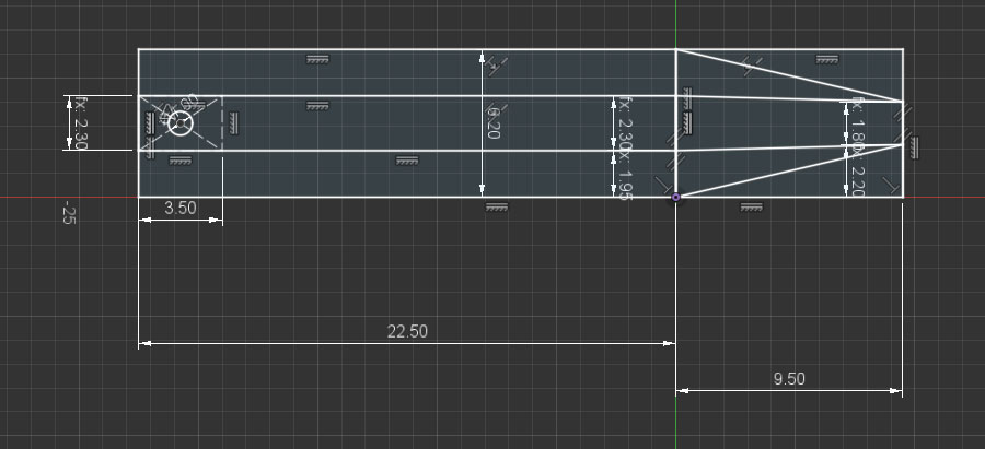
After some measuring and doing a few 3d-printed prototypes, I arrived at this design:


based on this sketch


with the base extruded 1.2mm and the top extruded 7.1mm.  The pointy "triangle" end was mirrored, and the entire length when done and adjusted was 36mm.   

These didn't have a clip or a button protruding at the bottom to help "snick" the connector into the plastic base's hole, but then I found the tolerances too tight to slide them in anyway, unless there were some kind of spring mechanism to the clip.  So, I chose to make the connectors easy to print, and I really cared, I could glue them into place.  I ended up printing about eight of these.

3. S.C. Ruffey bumper


The cars come with circular bumpers at each end.  One of those on the S.C. Ruffey car was severely bent, so I ended up breaking it off and re-glued it with CyanoAcrylate glue.  That worked well.  It's an area of the car that would only be under stress in a thrifting bin, not during normal operation.

4. Train car coupler springs

Each car has a latching connector that swivels left and right, and also bends up and down.  Many of these were broken. 

The mechanism basically relies on a spring made out of plastic.  My initial solution was to use a rubber band, but eventually I designed a simlar plastic spring.  Mostly, this was just a challenge to see if I could make one.

This is an example of a broken spring on a car.


This is the replacement "spring".


It's based on this design:


 The sketch for that looks like this:

Given the sketch, I used a "square pipe" operation along the curves to get the more challenging part of the piece built.  I chose a square pipe as opposed to a cylindrical one in order to avoid 3d printing problems.  

The curves were initially created using a bunch of circles, and then I trimmed away the arcs that I didn't want.

The central part with the screw hole is extruded 2.1mm.  The peg is extruded 2mm, but could be even smaller as it barely fits into the hook hole.

The challenge with this piece went further in that you have to be careful about thickness generated by your 3d printer.  You really want the curves to be a single line of filament thick.  If you have two lines, it gets too thick and inflexible.  After exporting this piece in .STL, I would load it up in PrusaSlicer and check to make sure what it was doing, and then iterate.

Here is the spring, mounted on the car.  You can see how it bends from the mounting plane in order to slot into the hook's hole, and on top of that, it has to be able to bend left or right as the car moves.


The problem now is that I printed these out of PLA, and that gets brittle in a short amount of time.  Eventually, it breaks, like this:


So my next steps: re-print these in ABS, try "welding" the original springs in cases where I have them, and/or try to rebuild the whole car-to-car connector mechanism so I don't have these funky hooks.

5. Thomas - eyes

Thomas arrived a little scuffed up.  His eyes were poked in.  His top was missing.  And he was missing the "lantern" on the front right.

I also didn't really know how Thomas worked, electrically.

In order to fix Thomas's eyes, I unscrewed the base from the top, and found that each eye was just plastic semi-sphere connected to an arm with a funny rectangular "hook".  Since I had opened up the machine, it was plain to see that the train had some geared motors -- one to move the wheels, and another for the eyes.  I presumed they were DC motors.

With some patience, I was able to align the eyes while re-assembling the top and bottom.  That's just physical alignment, nothing special.

6. Thomas - power

After some reading I figured I was missing a 16 VDC variable power supply.  Ideally, that would have a reverse switch, too.  I noodled on this quite a bit, thinking I'd make a 555 timer PWM controller for it.  Some sites say PWM works on some trains, but some others have electronics (noises, smoke, etc.) that don't play nicely with PWM.  For this train, it's just engine power, so PWM would work.

I couldn't find my 555's -- I know they're around here somewhere... -- so I ended up just using a lab bench power supply to get the train moving.  I ohmed out the pins, and found that the 1/8" stereo connector was only using two of its three pins.  The tip was not connected.  The middle and "barrel" (the ring closest to the wire end) were.  I have the connector set up such that the power supply is outside the track oval, and that means I can use ground on the barrel and V+ on the middle ring to go forward.  

I just used alligator clips to connect the power supply to the 1/8" plug.  Some day, maybe I'll rip an 1/8" jack out of something, and make a proper connection with a DPDT switch so I can have movement in reverse without messing with the alligator clips.

With around 6V power, the engine ran!  It was a little squeaky, so I dabbed a little sewing machine oil at the points where the train arms connected to the wheels.

7. Thomas cab

Thomas was missing his cab front, back, and roof.


Fortunately, there are slots that the front and back walls can fit into.  Calipers provided a good idea of the distance of slot bottoms to the roof level.

For each, though, there are round portholes and it wasn't as easy to figure out how to position those.  What I did was find a head-on view of the train on the web.  That gave me rough proportional distances and sizes, so I could figure out reasonable porthole dimensions and positions.  That also gave me a decent idea of how high to make the top arch for those pieces.

The next problem was that the front wall would run into the cylindrical tank of the engine.  The good news there was that the tank's diameter was pretty cleanly measurable on the original, and using some proportional positioning, I could figure out its placement with respect to the roof height.

This is what the model looked like for the front and back walls.  I did the front wall first, and then copied it, and extended it downward (without the tank arch) to form the back wall.  Each is extruded to 1.6mm thickness.

This is the sketch of the front wall

The back wall ended up being 39.2mm from slot base to the place where the right/left sides meet the arch.

A few corrections on this could be made.  The front wall's tank arch is a little shallow, so the piece tips a bit.  Also, both front and back would have been modeled better with the right and left side walls taken into consideration, so that the roof would have had some overhang.

Both pieces were printed flat on the 3d printer, and the face that met the heated bed was used as the outside, since it came out smoothest.

The front and back walls were painted with Testors light blue enamel paint, blended with some dark blue paint.  But, I didn't notice that the light blue was flat, where I should have had glossy; and the dark blue paint was acrylic instead of enamel.  It's close, but not perfect.

The front, at least, is supposed to have yellow trim around the portholes.  I used Testors light yellow enamel for that.  

I printed another circle to go in the circle of the portholes, and added a 9/32" hole in the middle of it.  The disc went into the porthole, and then the whole thing went onto an old record player.  I got that spinning at 33-1/3 RPM and gave it a few coats.  


In retrospect, I would have been better served to have made a separate porthole trim piece, printed it and painted it separately, and glued it into the front wall's porthole.  That would have made for much cleaner painting, and of course dimensional accuracy (compared to me, holding a paint brush).

8.  Thomas roof

The roof piece was modeled after having created the front and back walls.  Those gave me the dimensions of the top arch.  The head-on picture from the internet gave me a sense for thickness.

Oddly, I don't have the 3d model for that part any more.

For 3d printing, I printed it vertically, so that the layer lines would go horizontally (port-starboard relative to the train, lowest layer in back, highest layer in front) with supports.  It printed well, though the area where were supports ended up wavy and ugly.  No matter, that part is hidden behind the cab's back wall.

I sanded the roof top down quite a bit, and then gave it several layers (thinned) of Testors glossy black enamel.

Prior to sanding and painting, things looked like this:


9.  Thomas lantern

After I was all done, I thought I'd build the lantern that was missing at the front of the train.

It's supposed to go where those holes are.  The holes are about 11mm apart, and can accommodate at least 1.6mm OD (including sheath) hobby wire.

Here are some iterations of prints that I did for the lantern.

 I looked at a bunch of videos and pictures, and modeled it initially as a sphere within a cylinder on top of a loft-extruded base.  I printed it with the base on the build plate.

There were holes on the original train that presumably held the old lantern in place.  In my v1 rendering, I just had holes in the base of the lantern, and thought I'd have screws coming up from underneath to hold it in place.

However, the base of my lantern was so thin (2mm extrusion) that I would have a hard time getting a screw to bite into the plastic and hold, and yet avoid poking through the top.

My v2 lantern used the same model as v1, but I just added pegs going down, and sliced it with a plane from left to right.  That allowed me to print both halves and glue them together.  In doing that, the holding pegs were also split in half.

That looked good and functioned pretty well, but the seam was quite visible.


 But I wasn't satisfied with that.  I decided I really wanted it to light up.  I re-modeled the lantern with the idea that I'd have an LED inside, rather than having the sphere.  This is what it ended up looking like.  Compared to v1, it obviously has a hole cut out for the LED, but also a more attractive side structure, and it's thicker in front. Why?  Because in its original form, the front was so thin that light would shine through the plastic.


The based of the lantern has some slots that lead to the points where the holes reside.

From there, I took an LED and carefully bent its legs so that they fit in the bottom slots.  This was tricky, because I had to make sure the right amount of LED bulb was visible within the lantern, and the wires slotted in properly, and then were bent so that they would go into the holes in the front of the train.

This is what it looks like, all mounted up.


Once I had that figured out, I moved on to the electronics part.  The main part was a little circuit board that came from some kind of solar-powered light.  It had a latching push-button switch, and a Q5252 circuit board on it, and a 4 ohm resistor.


 The Q5252 is a cute little thing with very poor documentation.  Basically, it appears that it can be powered from 0.5v to 1.5v, and then it provides a boost mechanism to get to higher voltage, if you attach an inductor.  I didn't have an inductor, and there wasn't one on the board so I left that off.

The Q5252 also provides contacts for connecting a solar panel to charge a little Lithium Ion battery.  The solar panel was missing, or I'd already snagged it for some other project.  I de-soldered the battery terminals, and wired those to a AA battery pack so that a single AA battery could power it.

In an isolated test, I verified that in that shape -- no inductor, no panel, single AA battery -- I could switch on an LED and leave it on safely without burning it out.

As such, I replaced the LED output of the board with wires connected to a screw-down terminal block.  I then added wiring from the lantern's LED legs and clamped them to the circuit, and tested it.  Satisfied with that, I 3d-printed some clips to hold the wiring, glued the lantern and clips in place, and then just put blue tape over the remaining wiring so that the battery pack and circuit could reside in the cab.

Here's what a clip looks like.  The shorter flat glues upward to the base of the train.  The slot size is specifically designed for the 24ga silicone-coated wires that I got for another project.  They measure out at about 1.6mm OD but can squish down to around 1.45mm.  As such, the entry point (top, left, in image below) has to be wide enough for the wire to get in, and the slot itself is a little tight so it holds on to the wire nicely.

While it'd be nice, visually, to have chamfered or filleted corners on this, I just left it as is.  I checked against how it'd actually be rendered in PrusaSlicer to make sure it'd be sturdy.  Having chamfers or fillets sometimes makes for more retractions and skips in the print.

This is what the clips and wiring look like under the engine (laid down sideways).

I chose to send the wiring up the side of the engine, rather than drill holes.  I also chose to use the AA battery pack to simplify the electronics.  If I were to run the light off of the track power, I'd have to contend with a +/-16VDC voltage swing -- so... rectifier, step-down, etc. -- and then drill a hole somewhere in the body to feed wires through.  That's all doable, but at this point I just have some things glued on, and no holes drilled.

Here's a side view, where you can see the battery pack, etc., ingloriously lumped into the cab. 

And here's a view with the light turned on.


Done for now!

Here's Thomas running at about 10.5v.  He has a tendency to de-rail currently, probably because several of the PLA coupler springs are broken.  Or, maybe he de-rails because he's trying to stay true to the original TV series.


Will I sell the set?  Probably not.  It's nice enough to think of taking it out each Christmas.

Friday, June 10, 2022

Drilled dithered dog

I was presented with a wonderful little 3018 ProVer CNC mill a little while ago.

After a test run with it, where it cut really clean isolation channels for a PCB, I figured I could move on to doing something artistic.

I decided to make a "grayscale" image of a dog by drilling lots of holes in a black surface.  The black surface I found was a "chalkboard" from the $1.25 store.  It's basically 3mm pressboard with some kind of plastic surface.

The variations of light would be achieved by using different size drill bits: 0.6mm, 0.8mm, and 1.0mm.

Here's an example dog:


In order to get a good result, I did some Photoshop magic to eliminate details:

Then, I converted to grayscale and assigned a black background:


and then rotated the image to match the layout of the physical material that I'd be drilling:

Through experimentation, I found that playing with lightness and contrast on specific areas, and adding a bright highlight edge would provide a better result in the end.  Note how I brightened the eyes, and upped the contrast overall here.

Coding

To reduce the image in resolution and color space, and to generate gcode for drilling, I used a combination of Python 3.9, Python image library (PIL) and numpy.  For a coding environment, I just used IDLE.

Hexagonal pixels

My thought around how to lay out the drill holes was to use a pixel pattern comprised of equilateral triangles, rather than the typical "square pixel" kind of layout we're used to.

The holes ended up being 1.4mm apart so that if I had several 1mm drill holes next to each other, there still would be enough "wall" remaining to prevent breakage.

If I were to have a traditional X/Y grid of pixels, each hole might be 1.4mm apart along X or Y, but along the diagonal, a hole would be 1.4mm * sqrt(2) from its neighbor.

Instead, I chose to use equilateral triangles.  That means each hole center is 1.4mm from all six of its neighboring holes.

To achieve this, I could march 1.4mm along a given "scanline" on the X axis.  As I'd move Y along, it would move that step amount (1.4mm) * sqrt(0.75).  Do some geometry and you'll see where that came from.  On every other scanline, X's starting location would be half of the step amount.

Each drill point could then be mapped to the original image resolution, or vice-versa.

Averaging

I take the center point of the mapped pixels in the original image, and grab a square of pixels from it.  Then, I use numpy to logically "AND" that with a (255,255,255) circle whose diameter is the same as the square.  It's not exactly the hexagonal pixel it should be, but it's close enough.

Once I'm done with that, I have only a "circle" of the grabbed pixels, and I can just compute an average of the non-black pixels.

Since I'm dealing in grayscale values -- but with an RGB-type image -- I end up with pixel values like (5,5,5) or (142,142,142).  All the R, G, and B values are the same for each pixel, and each is in the range 0..255.

From there, I make a crude attempt at mapping the 0..255 values to the drill bit size that would emit a corresponding amount of light.  I'm doing that very crudely right now, just dividing the 0..255 value by a divisor.  The higher the divisor, the darker the result, and vice-versa.

Visualization

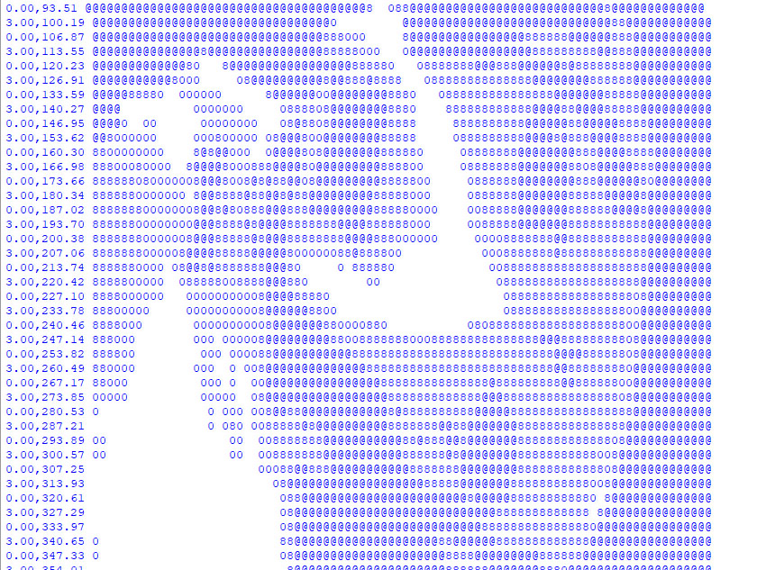
I added a few things to help visualize what was going on.  At first, I printed an ASCII character to represent the darkness and lightness of the holes as they were being generated.  These wouldn't come out in a triangular/hexagonal grid, but would give me a rough idea if I was getting the right result.  Also, it would be more vertical than horizontal because of how our fonts work, typically.  This is an example of some of the output:


(The numbers on the left of each line were just confirming to me that I was alternating X positions on every other scanline.)

Image rendering

Once I was satisfied with that, I added code that would construct an actual image, creating white circles of appropriate size for each drill point.  This is a more accurate representation of what the physical result would be.

The initial implementation did straight-up averaging and no error distribution (dithering).  I found that generally a lower divisor would give a better result.  This image is no dithering, divisor 3.65.


Dithering

With a little bit of coding, I added dithering, which would distributes the light energy error to neighboring pixels (one to the right, and two below).  "Error" here is defined by the amount of light coming out of a given hole (math out the PI*r^2 of each drill bit) compared to the average light value I computed for the average of the pixels in a chunk from the original image.

Each of the right, down-left and down-right pixels receives 1/6th of the error energy, so it's all done in one pass from top to bottom.

The image below has dithering turned on, 1/6th distribution of error to neighbors, and a 3.95 divisor.


The overall result from dithering is noisier but, in ways, more detailed.  You can see a little bit more detail in the dog's nose, ears, and chest "coloring" with dithering turned on.

Satisfied with the simulation, I did a simple conversion to gcode.  As I would draw each dot on the simulation, I would add the location to the appropriate drill bit's set of coordinates.  So, each drill bit gets its own array of places to drill.  

I then iterate.  Each drill bit gets its own gcode file.  I then walk through each location and issue the appropriate commands to lift the milling head, move, descend slowly to the surface, and then drill through the material.

I thought about making the code a little smarter about nearest neighbor computation to reduce the travel time of the milling head, but decided that's not worth the effort.  I can just let the mill robot its way through, and perhaps it makes for a more accurate result if I'm primarily moving left to right.  (Backlash by doing lots of pos/neg movements might make the result wiggly.)

Milled result

The milled result is pretty darned good.  The only real problem is that the surface of the "chalkboard" has a tendency to tear, so I ended up having to use a Sharpie to blacken the pressboard where the surface was lost.


Lighting

While the initial result was pretty cool, the better result comes from backlighting.  Here's what it looks like with just monitor white behind it.


Shadow boxing and more lighting

I headed out to the nearby Goodwill and found a few shadow boxes that I could repurpose.  That would serve as the frame.  It was a cheapie home decor item with some kind of thing that would seem cultural inside.  I used my hot air gun to melt the hot glue that held the back in place.

I also had had the good fortune to have found a Lampeez "3D Lamp" on a prior thrifting adventure.  Those lamps just edge-lit acrylic with a drawing on top, laser-cut (apparently) to the borders of the drawing.  They're not really "3D", in my opinion.  They're about a 3D as my dog chalkboard.

The Lampeez base has interesting stuff in it.  It's powered by battery or USB, and it just has a board inside that does some magic and turns on some SMD LEDs.  There's a touchless switch mechanism that uses a single wire like an antenna.  Newer ones come with a remote control and the board sports an IR receiver.

I took the Lampeez PCB and desoldered its touch sensor and IR receiver, and then added extension wires to each.  The touch sensor wire's end is connected to a small piece of metal -- just a 1" x 1" piece of aluminum foil is all it takes -- in order to work again.

I taped a sheet of white printer paper on the back of the dog chalkboard to help diffuse the light.  Then, I mounted the Lampeez PCB to the back panel of the shadow box.  I cut a little hole in the back of that panel to allow the USB power line to come out.  (If someone wants, this could be replaced by battery power and a switch, instead, but you'd have to make it rechargeable.)

The aluminum foil antenna is just taped to another place inside the back panel.  A touch on the outside of the panel activates the switch, and pressing and holding there will turn off the device.

The IR receiver is taped to the back panel, and faces the front of the box.  As it turns out, the holes in the dog chalkboard let the remote control signal through to the IR receiver, so that works like magic without have to add a special hole just for that component.

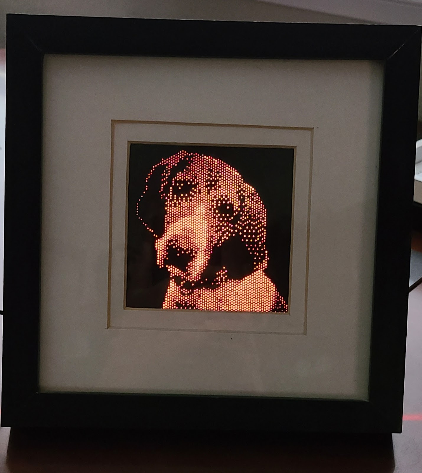
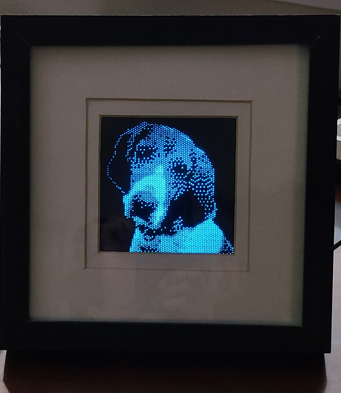
The end result currently looks like this.  It's presenting a square result right now, just because that's how I found the matte of the shadow box.  I might change that up so more of the dog can be seen.  The remote control lets me set different colors, or go into a mode where it fades across different colors.


Before and after

"Pixel" shape variations

The original code just drew a circle for each chunk of original image pixels that would be averaged.

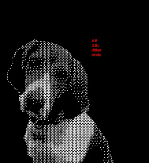
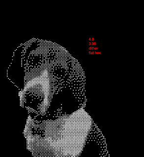
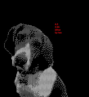
I tried a few alternate implementations where I draw a hexagon -- either with flat top or flat sides.  In theory, that would provide a more accurate representation of the original data.  But that doesn't necessarily mean you get a more aesthetically pleasing result.

What it means is that along with choice of physical size, dithering, and divisor (aka gray-to-bit size mapping), the chunk pixel shape can provide more options for how the end image will be built.

Here are comparisons.  In order, they are pixelShape = circle, flat-top hex, flat-side hex.  If you look closely, you'll see differences in the dog's right eye, brow, and nose.  If these were overlaid, you'd see many other subtle differences.

 
pixelShape = circle