Full Spectrum Laser Hobby laser - alignment
I'm posting this after getting very far into reviving an old Full Spectrum Laser hobby laser. It's 4th gen, I think.
In short, the machine was in rough shape when I got it, which also explains why I got it for a relatively low price. Among other things, it had problems with its power port, input air line, and front panel switches. It had good water cooling tubes, but no chiller. The inside light wasn't working. The locks were missing keys, but luckily they were all in an unlocked position. There was no honeycomb. It had no air exhaust pump and its rear panel for the air exhaust was missing, so there was just an odd, rectangular hole in back.
Most everything else turned out to be working well. The interlock switches on the front and rear panels were good. The power supply was good. The driver board was working. And, of course, the CO2 tube itself was still working. I couldn't test any of this when I bought it, so I consider myself lucky. I also found inside the "Ruler" for doing Z height focusing.
Texting, texting
My first test of the laser -- with safety glasses on! -- was to fire the laser using the "Text" button on the power supply. Yes, it says "Text", not "Test". That gave me confidence that the tube itself was operational. I only did that after having thoroughly cleaned a fountain pump that I'd gotten at a thrift store, and set up a Homer bucket for cooling.
From a power standpoint, I run the laser, water pump, exhaust air pump, and nozzle air pump all off of the same power strip. The water pump and exhaust pumps are not switched, so when the power strip is turned on, they come on immediately. This is done for safe operating reasons. The way it's set up, I can't fire the laser without the water turned on. (And the gurgling of the pump reminds me to check to make sure it's ok before turning on laser power.)
Pushin' my buttons
While the initial test dot fired using the Text button, the front panel buttons for testing the laser did not work. Eventually, I found that the old front panel switches were broken and weren't trustworthy. The Laser enable latching switch, in fact, popped its back off when I depressed it, breaking the switch entirely. (BTW, one thing I really don't like about this machine's design is that if something breaks and falls into the power area, there's a decent chance that parts will fall into the power supply fan cage.)
I bought a two set of 12mm / 0.5 inch push button switches -- some momentary, some latching -- de-soldered and removed all five old switches, and put in the new ones.
Along the way, I found that the Laser enable switch is set up in series with the door interlocks. Also, the two laser test buttons are wired in series, which explains why the front panel says you have to press both to test-fire the laser.
The front panel's current control (precision pot) was wired to a three-pin header on the power supply. There also was a dangling, single-wire connector coming from the control board, and it sure looked like it should go to the current control, but I left that alone.
Software, test cuts, and FSL to the rescue
I got great support help from Full Spectrum Laser, even though the machine is out of warranty. They were most excellent to work with. The machine is kind of a predecessor to the popular K40 machines of today, but its driver board is specifically for use with FSL's Retina Engrave software. After some searching, I found a version I could use. But it didn't really work.
It turns out that you have to get a specific version of the
software to run a machine as old as mine. Yes, you can get the old Retina Engrave if you look around a bit on their site, but you have to get the right version for this generation of the hobby laser.
Once they steered me to the right version, things were much happier! I could start Retina Engrave on my laptop, connect to USB, and it would connect. (If that didn't work, I was probably going to have to head down the path of getting a K40 control board and LightBurn.) I could get it to test fire from the software.
I did some test cuts. While I could get some things to burn, I noticed charring on the wiring of the red-dot aiming LED while I was doing some etching tests. Yikes!
I powered things off and left the machine alone for a while, realizing I'd need to go through the alignment process.
It took some time -- really mostly to get up the nerve to do it -- but I eventually watched the YouTubes and went through the alignment steps. The first mirror was very poorly set up. Once it was in place, amazingly, I didn't need to do anything to the second mirror or third mirror. But until the first mirror was fixed, I definitely could see that the laser was aiming at the back side of the cylindrical third mirror mount, and so it was probably bouncing off and into the wiring.
Prototyping the cow
I'm adding a piece to the FSL here as a test, seeing if this approach might later work on a friend's K40. His laser has been aligned from mirrors 1 to 2, and 2 to 3. But nothing is coming out the output tube.
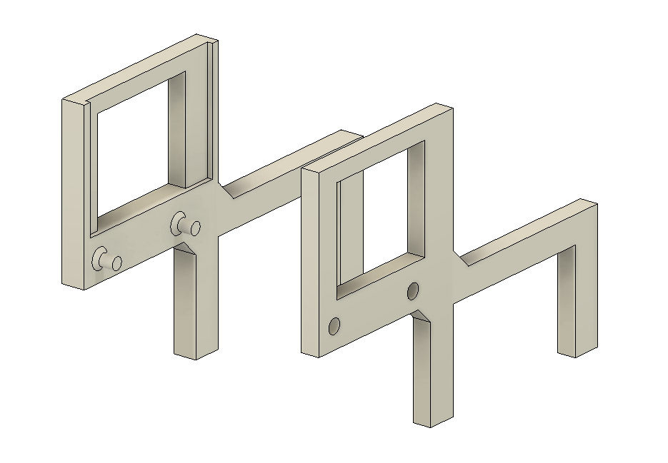
Hence, the cow. Here is the cow, designed and rendered Fusion.

The cow is basically a target holder. It sits on the gantry in a somewhat predictable and precise way (yes, "somewhat precise"), and is meant to hold a piece of paper. I don't have the original schematics/dimensions, and don't want to disassemble what's working. So, I made the cow to help determine where the laser is actually hitting, relative to the gantry bar.
I built the cow with the intent of 3d-printing it. Since 3d printing has its quirks with respect to dimensional accuracy and shrinkage, I made its legs wider than the bar depth (distance in Y) intentionally, thinking that I would shim it or drill a screw to get it to hold onto the gantry snugly.
The design splits the cow in two. I used a few printed pins and holes to line up the parts. I used 1mm chamfers to strengthen the joints where the pins met the left part of the cow.
I subtracted the left side from the right side to create holes, and then widened those by an extra 0.3mm to allow for shrinkage. Doing it as two halves made it easier to print flat, and helped avoid problems with supports. Note that the "left" side of the cow has a rectangular area cut out. That's there so a piece of target paper can slide in from the top after the two halves are joined.
In real life, I printed the cow using white PETG with 0.2mm layers. The pegs had some extra gunk when done printing, but I could clean them up with flush cutters. The two pieces could be joined after that with a satisfying squeeze. I didn't bother to glue them.
This is what the cow ended up looking like, printed and joined.
 |
| Printed cow, PETG, 2 sides joined |
As mentioned before, I made the legs of the cow intentionally wider than the gantry bar. I chose to do that rather than spend time on a test print and making it totally accurate. What would have been a big waste would have been making the legs too close together, and unable to fit over the gantry.
I found a random magnet that worked well as a shim, and that allowed the cow to fit snugly.
| Random sheet magnet as a shim |
These are back and front views of the cow, mounted with shim on the gantry.
| Rear view with shim in place (friction fit, not magnetically attached) |
 |
| Front view, mounted on gantry |
I cut out, very crudely, some 40mm-wide pieces of paper to act as a first target.

This is what the paper looked like in the head of the cow.

Time for an initial test fire! Power dial 3 turns, quick hit on the test buttons, and, poof, we have a hole.

The next step was to build some actual targets. I used Inkscape and threw together a page with 40 mm x 40 mm grids, with lines spaced 4mm apart.
The following are mountings and test firings.
Grid target 2, and grid hole 2:


Grid target 3, and grid hole 3:


Here are holes 2 (lower) and 3 (upper) for comparison.

In both cases, the target grid was flush against the left side of the mount. With a little magic help from Adobe Photoshop Elements, I clipped out the Target 2 result above, positioned it, de-tombstoned it, etc.

End result from target measurements
The bottom grid line is at pix 834. Next grid lines up are 756 and 678, meaning the photo is showing 78 pixels per 4 mm. The hole center is at pix 688, so it's 10 pixels below the grid line. That means it's about 4mm + (68/78) mm, computing out as (4.872mm) above the bottom. Also, the hole is pretty much dead on 20 mm from the left edge of the page.
What's Next
Now that I have a pretty good understanding of where the hole is hitting, and because I know the laser is well aligned, I need to make a cat laser pointer that will point through the hole. Ideally, I'll have a second cow-like mount, placed on the gantry closer to the x=0 point.
If I can make the cat laser's starting point close to same as the hole, shine the laser down along the gantry and through the hole of the target, it should go through to the output mirror and down.
That all should enable us to do 3rd mirror adjustments without actually using the CO2 laser.
No comments:
Post a Comment