Saturday, April 5, 2025

WALL-E revival

 Yay, a WALL-E with treads showed up at the thrift store!

 I've had a WALL-E before, but it was a cheapy where the treads didn't move.  In that one, instead, there were motorized wheels sticking out under the treads.  I thought: even if this doesn't work, I can hack a new microcontroller, etc., into it just for fun.  But after playing with it, I found that the tread movement is a huge part of what makes it fun, so I ended up sending that one back into the stream.

 But this one, wow, this one is the real deal.

It's a WALL-E made by Thinkway.  There isn't an obvious version or date on it.  Under the front lip, "T90209" appears to have been heat-pressed into it as a serial number.  The label reads, "I'm a Thinking Toy" and "THINKWAY TOYS".

Here he is.


WALL-E arrived dirty but promising.  There was a serious amount of grime all over, as if the previous owner had it in a dusty garage.  Amazingly, the battery compartment still had its cover, and the inside contacts did not show evidence of corrosion.  So often, I find toys in the thrift stream where the battery cover has been removed so that batteries don't end up going into the waste.  That's great, sure, but then they don't put the battery cover back.

 He did not have his remote control.  But, there is a "play" button on the top of the front chest area.

After doing some internet searches, I found that this tread-type WALL-E may be one of the earlier models they made.  It's likely a "U-Command" WALL-E.  Those sell for $100 to $500 on e-Bay. 

With some fresh batteries in place, I wasn't getting the kind of behavior I'd hoped for, so I decided to take him apart and do some fixing.

There are at least a couple of good WALL-E repair videos.

This one shows a WALL-E that takes three horizontal batteries, whereas mine takes 4 AA vertically.  Perhaps that's a US / European difference.

 (Fix It Ade, partial fix) https://www.youtube.com/watch?v=B3MTJLdCoYo

(1nformatica) https://www.youtube.com/watch?app=desktop&v=kq-pym-aO4c

The latter is closer to the one I have, and exhibits some of the problems I found.  But mine had other problems (some of which I may have been responsible for).

In the end, mine had these problems

- Poor soldering / strain relief caused complete power loss.  Easy fix.

- The IR system was failing intermittently, possibly due to bad soldering.

- The front IR detector had poor soldering / strain relief, causing the signal loss.

- The IR transmitter was missing.

- The port-side axle gear was broken

- The starboard side axle-to-gear connection was stripped

Disassembly

Much of the disassembly follows what was shown in the 1nformatica video.

Prep

Set up a holding bin for parts

  • The battery panel
  • Tamper-resistant/security screws from the back panel
  • Four base screws (holding wheel assembly to torso assembly)
  • Three screws each for the wheel assemblies
  • Two screws holding the rear IR board
  • Two decorative side flaps above the rear axles
  • Possibly seven flanged screws for the motor mounts
  • Possibly two more screws for the front IR board, and two more that make it hard to get to

Power off

Set the power switch to Off
 

Remove the battery panel
 

Remove at least one of the batteries


Back panel removal, disconnect, and return

Remove the four security screws to release the back panel


Gently open the back panel, and remove the screws holding the rear IR board.  Tuck it inside the torso cavity.  Put the back panel back in place with one or two of the top security screws.
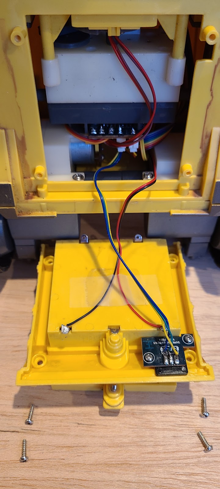


Base-torso separation

Place WALL-E face down
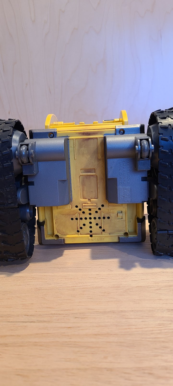


Remove the four base screws


Remove the rear-most screw from each wheel assembly.  This screw is in a recessed area, and holds the wheel assembly to the torso.  The other two screws in the wheel assembly hold the wheel assembly itself together, and they do not need to be removed.
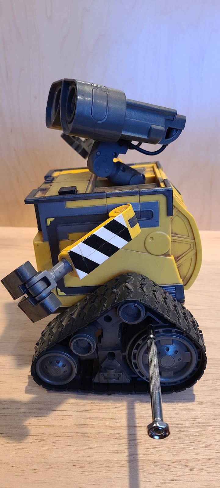

Gently pull away the base from the torso in front, and you'll see that you can't get the base off unless you gently bend the wheel assembly off its side pin.  


Once you do that, each side will be released.  With each wheel assembly pulled away from its mounting pin, separate the base assembly from the torso assembly.

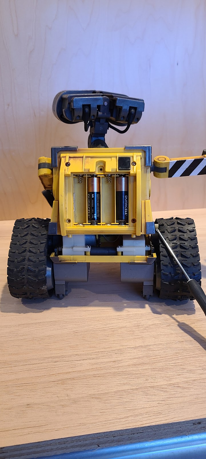


With the assemblies separated, you should be able to rest the wheel assembly flat (treads on the ground, as normal) with the torso-head portion still face-down.


Base-torso wiring separation

At this point, the main motor board will be visible.  Disconnect the connectors for M2 (arms/eyes motor, 2 pins), M1 (wheel motor, 2 pins), 


and power.  


 Then, gently remove the 8-pin sensor connector from its header.  


Be very careful when prying the connectors out of their headers.  Don't just pull them.  I did that and it pulled the header out (but left the pins in place, luckily.)  If you have to repair these, I think they're probably PH2.0 headers for M1 and M2, and an XH 2.54 header for power.

With these removed, the torso assembly is now completely disconnected from the base assembly.  

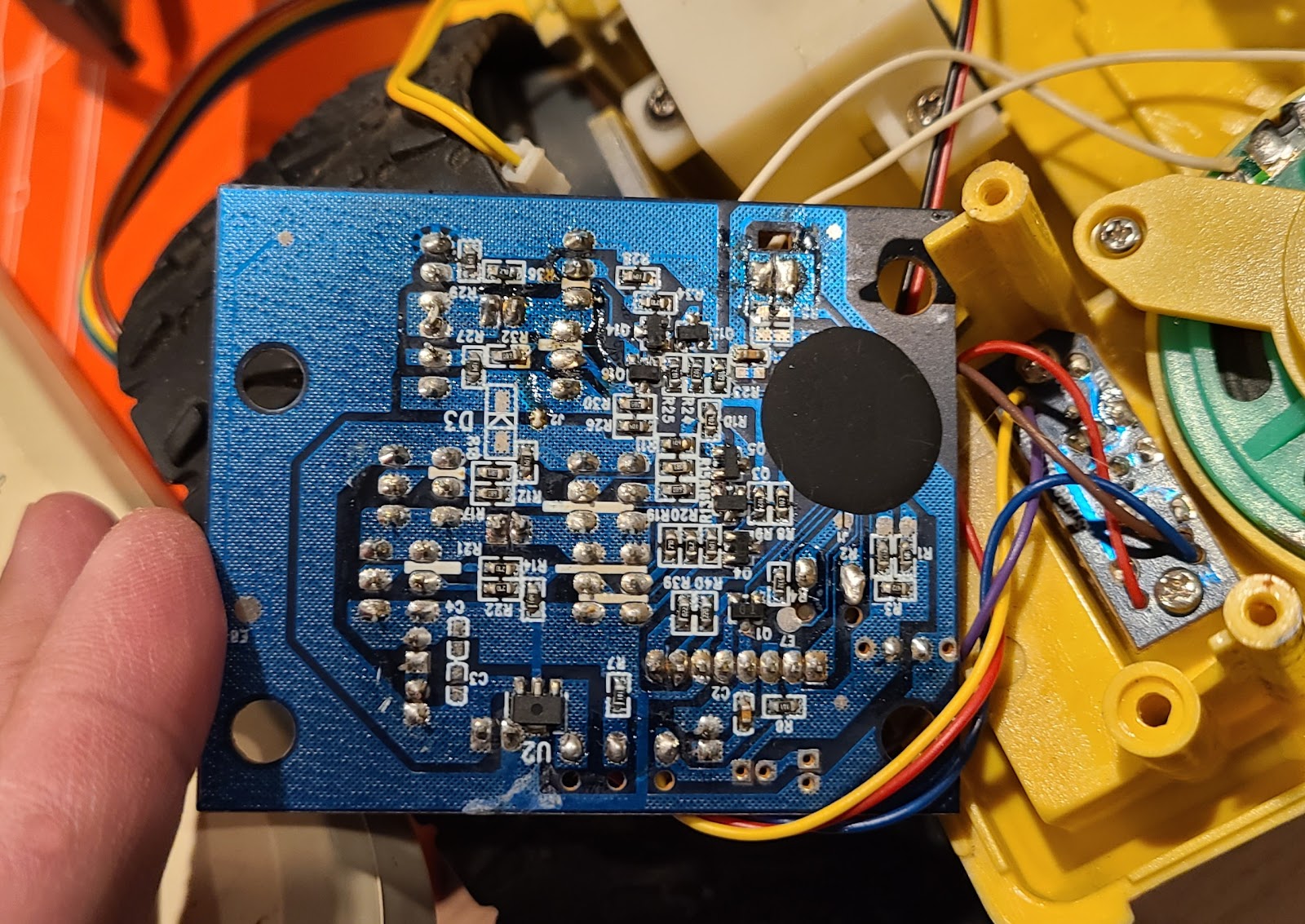
(For possible future reference, this is the back side / underside of the main board.  I removed it to look at the connections to see if anything appeared fried, but it looked good.)

The torso's inner connector board

We had disconnected the rear IR board earlier.  Inside the torso, you'll find another connection board.  That has two headers.  One is a 3-pin, where the rear IR board's wires click in.  The other is a 2-pin that is for the Play button.  


 (Torso connector board with 2-pin Play button connector removed)

The board also has hard-wired to it the 3 wires for the front IR board, and those are connected in parallel with the rear IR.  The eight-pin ribbon from the base assembly also has its individual wires hard-soldered into this board.

(Back side of Torso connector board.  Note fat traces connecting the two sets of IR sensor wires, 3 each, together.  Also note: possibly insufficient solder in one of the set of IR sensor connectors, and excess wire sticking past 8-wire solder points, potentially risking shorts.)


All in all, the 8 wires are for

  • 2 Play momentary switch / button.  (Any biasing of signal is done on the main board.)
  • 3 for eye LEDs (Presumably these are: two signal, the other either power or ground; each signal line probably can be or is PWM-controlled and has appropriate inline current resistance.  I don't think there are SMD resistors on the board, so I suspect any inline resistors are on the main board.)
  • 3 IR signals (in parallel from both sensors).  (Presumably, power, ground, and signal, though each IR board uses the terms R-, R+, and R0.  I didn't check to see which is which.)

Remote control

My initial focus was on remote control.  If I were to run WALL-E just using the Play button, the movement would be haphazard.  I wanted to find out if I could cause it to just go Forward or Reverse.

After some searching, I found a few promising documents online.

First, there's this Arduino page

https://forum.arduino.cc/t/u-command-wall-e-who-has-one-looking-for-ir-code/552285/11

that leads to an http (not https) page

http://www.hifi-remote.com/forums/viewtopic.php?t=12137

Its August 01, 2003, post has a listing of timings and IR codes.  It says there's a lead-in of 6000 microseconds (us), then 4 data bits, 8 data bits, a repeat of the 8 data bits, and a lead-out of 2000us.  Apparently, that sequence repeats three times for all commands except joystick fwd and reverse.

Each bit is represented by +1500 / -500 for a "1", and +500 / -1500 for a "0".  

For all the "+" values (the lead-in, lead-out, and some portion of the 1 and 0 bits) we're supposed to generate a 44 kHz pulse wave.  This is provided in Arduino code by the IRremote library.  We can call IRsend's sendRaw() function, passing in an array of 16-bit integers for on and off times.

The behavior we'll be seeing is similar to what is shown in EEVblog #506

https://www.youtube.com/watch?v=BUvFGTxZBG8

I found another set of WALL-E data in the github repository Lucaslhm/Flipper-IRDB (in Toys > Thinkway_Toys > Wall-E_Robot.ir).  If you look at the codes there, they're mostly similar, but not all the same.  And, importantly the Lucaslhm ones show 38 kHz frequency with 0.33 duty cycle, whereas the hifi-remote ones were for 44 kHz with no duty cycle specified.  Also, the identifying code appears to be 1010 for both hifi-remote and Lucaslhm/Flipper-IRDB.

IRSend build

Lacking a remote control, I made a first attempt at building one.  Mine was comprised of

  • A breadboard and a typical smattering of hook-up wires
  • Two 330 ohm resistors in parallel (computes to 166 ohms)
  • A scavenged IR remote from a discarded TV remote control
  • An Arduino Micro
  • A visible light LED

I hooked up Arduino pin 3 (default IRremote library output pin) to the resistors to the LED cathode, and then LED anode to ground.  IR LEDs are pretty clear, so you can easily see which side has more metal inside, and that's the side that connects to Ground.

I measured the forward voltage of the IR LED at around 1.1V, and figured I had about 4.5V from power, so the current through the LED woulc be (4.5 - 1.1) / 166, or about 20.5 mA.  This is within the safe range for an Arduino pin, and also within the typical safe current range for LEDs.  For a visible LED, if the forward voltage is 0.7V, then the end result is about 23 mA.

I wrote a chunk of code that would then send the intended pulses out using irsend.sendRaw().

With WALL-E's power switch in the Play position (slide switch closest to the middle of the base) and a fresh set of batteries, I tried aiming the IR emitter towards him and... nothing.  No reaction from WALL-E.  Sad.

At this point, I had a number of possible problems or causes

  • The IR LED isn't working
  • The IR LED isn't bright enough or is facing other light interference
  • There's dirt on the sensor or transmitter
  • I got the frequency is wrong
  • I got the code wrong
  • The IR receiver isn't working
  • The inner workings aren't processing the IR signal correctly

Is the IR LED transmitter working?

I re-ran my sketch in a darkened room, and watched the IR LED using my phone camera.  When it ran, I could see a pink-purple light show up.  That was some proof that I got the circuit right.

Is there other light interference?

I separated out the rear IR sensor, and reflowed the solder for it.  


Then, I made my own jumper header using PH2.0 header and pins, some wire from an old ethernet cord, and an ethernet break-out board.  That allowed me to have the sensor outside of the main cavity with no other plastic in the way.   Still, nothing.

Is there dirt in the way?

I thought this might be a problem prior to knowing that the two IR sensors were wired in parallel.  So, hoping that maybe the rear sensor failed, but the front sensor was good and simply dirty, I cleaned up the exterior plastic of the front sensor.  Still, nothing.

The frequency is wrong, or I got the code wrong, or I got the bits wrong.

At this point, I looked at a variety of possible causes in the software side of things.

First, I rebuilt the sketch so that upon receiving a command "9" through the Serial interface, it would start looping through all 256 data byte values, and send them.  I didn't know how long a given operation might take, but just delayed a little while after each transmission.

I also noticed that the AI-generated Arduino code (given to me by searching "how to use IRsend") was passing in an array of unsigned int values.  But on a deeper inspection of the code, I found it was expecting to receive uint16_t, specifically, so I switched over to that.  (In the end, it didn't matter, but this is one of those C coding tripping points that a proper IDE would have flagged.)

I ran the code at 38 kHz across all 256 codes, and got nothing.  But then I tried again at 44 kHz and got a response, finally!

I added code that would emit the sequence and code to the Serial Monitor, and tied the input to a typical Arduino button, pulled low (with an extra 50ms delay for debouncing).   I also noticed that reactions didn't start happening until the last 128 codes, which was in line with what the posted timings showed.

That allowed me to click the button for each of the data byte values 128..255, and test for reactions.  Sure enough, I got reactions for specific codes.  Of those, only one was identifiable -- the Dance action -- because I'd seen it in the 1nformatica video.

In the end, I ended up with this table of U-Command WALL-E IR codes

 hifi-remote.com (44 kHz)

+6000, -2000, 1010, data, data, +2000 

codes: fe, fd, ae, ac, ad, ab, a4, a6, a5, a7

 Lucaslhm/Flipper-IRDB (38 kHz, 0.33 duty cycle)

+6000, -2000, 1010, data, data, +2000

codes:  fe, fd, ae, ac, ad, ab, a4, a6, a5, a7

 Mine found through experimentation

 44 kHz

+6000, -2000, 1010, data, data, +2000

codes: fd, fe, df, ae, ac, ad, ab, a4, a6, a5, a7, maybe c8 

So in the end, my WALL-E's codes and frequency match up better with hifi-remote, but not exactly, and there are mysterious extra codes.

Fixing movement

At this point, I was very happy to have a set of reactive IR codes, but couldn't really tell what each would do, because the treads weren't moving properly. 

I had removed the treads and placed WALL-E on a lift so that the wheels could spin freely.  (Note: I'd already made a pretty big mistake in doing this.  I thought a gentle way to remove treads would be to slide a piece of paper in, and rotate the wheels so that the paper would get under a wheel.  That worked, and I could slide the tread off easily.  But in doing this, I was forcing the rear wheel to turn when its axis position was fixed, and you NEVER want to do that.)

When running my IR codes to WALL-E, I could see one wheel spin, but with the tread on, it would not.

At that point, I got on to disassembling and removing wheel assemblies from the gearboxes on each side.

Getting the entire assembly of both wheels out from the torso is the first step.  The 1nformatica Youtube shows how to do that.


In between each gear box, there is a grey plastic cylinder with hex holes on each end.  That can be pulled off easily, leaving you with each side: a gearbox and a tread assembly.  One side also has the DC motor.  Its gearbox is more intricate.

I'm not quite sure how it works, but the system is able to make WALL-E turn with only one DC motor.  I think it's using momentum to cause a gear disengagement to happen. 

This is what the starboard axle gear looks like.  There may be a hairline fracture showing in the second picture (right side around the 3:00 position).  But, I think the problem with it was that the axle knurling had ground a groove inside the hub of the gear.


This is the port-side axle gear.  Clearly, there's a crack in it.  Based on other videos, this one could potentially be salvaged, but I went with my own 3d-printed ones, instead.


 This is an example of the 3d-printed gear, top and bottom.  Variations can be seen in the teeth and infill.  But, it does ok.  This is actually one of two spares I ended up with.  The others are in the gearboxes now.  It'd be really nice to have a resin printer to make these.  Using my current set-up (Artillery X1), they vary greatly in quality from layer to layer and on different teeth, even though I'm using a randomized layer alignment (Prusa Slicer).  That said, I wonder what material choices I'd have with a resin printer.  The model's pretty good.  The printed result is mediocre.


Port gearbox with motor and motor board

Starboard gearbox (with replacement 3d-printed gear in place)


Axle with knurled area
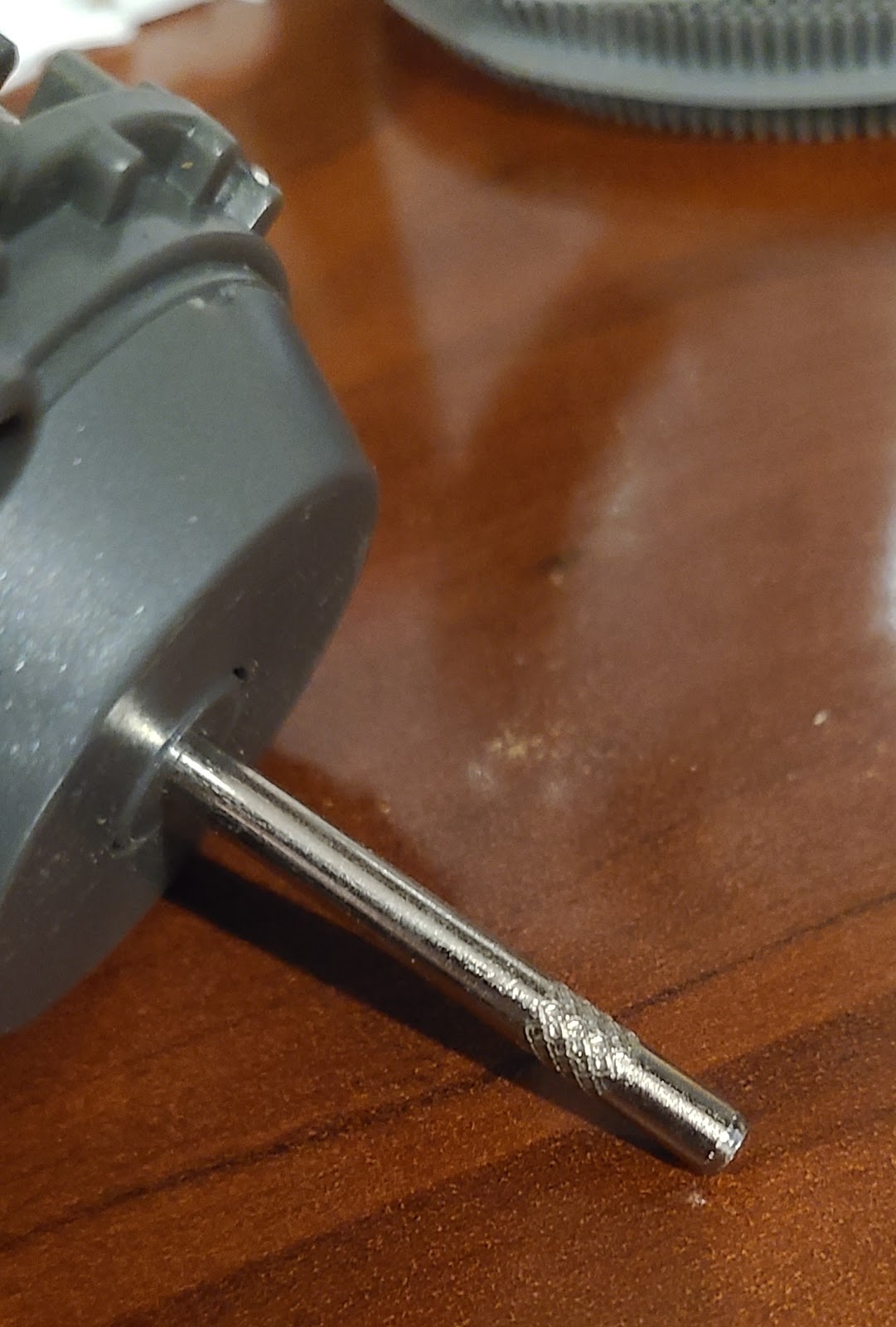


Getting the tread part separated from the gearbox is a pretty brutal step, and doing it can be damaging.  It turns out that each wheel assembly is probably press-fit onto the shaft as one of the final assembly steps.  I think even the tread installation is done before the tread assembly's axle is pushed in.  It was never really meant to be undone.  The axle comes out of a tread assembly, and goes into the gearbox. The knurling near the end of the axle joins to a kind of spur gear.  It is that same gear that is apt to break in two ways, both of which I experienced:

  1. The gear cracks due to age, thereby losing its friction grip on the axle.  The 1nformatica video showed a clever repair for that, reusing the existing gear.  Another youtube I saw suggested a similar problem with a zip-tie solution.
  2. The axle rotates while the gear is fixed, or vice versa.  The nylon gives way, leaving the knurled area spinning freely.  If this happens, the original gear is in one piece, but is not usable.  Perhaps with clever melting, it could be coaxed back to a working state, but it'd likely be fragile.  For this reason, NEVER ROTATE THE WHEELS MANUALLY!

Either way, to repair this, you have to get into the gearbox and replace the gear.  Due to the way they placed the gearbox's four screws, getting into the gearbox forces you to separation the axle.

Why, oh why?  The screws go into the gearbox from the tread side.  It would have been much better if the screws went in from the opposite side, so the screw heads faced the center of WALL-E rather than facing the port and starboard walls. 

Also, why press-fit?  If they didn't have press-fit wheels, and instead used a "set screw" way of holding the gear and shaft together, it would have been better.  But if that were to be done, the person assembling it would have needed access to the insides of the gearbox, and I think for "clean manufacturing" purposes, grease exposure/loss, etc., they made it so the gearbox was a closed system, only to be used once.

Well, so, we end up having to forcefully un-press the axle out of the gear.  This took some force, but I used a few extra random pieces of metal (US 25c coins) to prevent direct pressure against the plastic, and very careful turning/prying with a flathead screwdriver to get things apart.

The gear itself is a 12-tooth, 5mm-thick spur (?) gear with another 4.5mm-4.7mm cylinder on top.  It has a 4mm bore.  I printed one based on a Thingiverse model ("Thinkway U-command Wall-E gear & cap" by "Zadakleader635"), and then re-built it myself based on measurements

I re-modeled it using Autodesk Fusion and a gear generator plug-in.  (It's either that, or generate the gear vectors in Inkscape.)  I wanted to control the dimensions, mainly to compensate for material shrinkage of the inner hub and teeth.  I also liked adding my own chamfering.


3d-printed PET-G gears. (For my printer, I find I get globs if I print only one. so I printed sets of 4.)


The gear hole size is tricky.  It has to be sufficiently large to slide on the axle.  But also tight enough to engage the knurled section of the axle.  By my measurements, that's only a 0.15mm diameter tolerance.

In the end, mine was designed with a 4.2mm hole that shrank to smaller than 4.0mm.  After printing, I drilled out the hole with a 0.1575" (or, 4.0mm) drill bit.  I printed it with PET-G, which is closer to nylon in behavior and more resilient than PLA.

I also had to size up the gear dimensions a bit, to compensate for shrinkage.

After printing, I finished the teeth with a hobby file.  Then, I chucked the cylindrical part of the gear in a portable drill, and spun it at high speed and ran it against some sandpaper to remove the sharper edges.

 Putting it all back together again

For me, both gearboxes had an axle gear problem, but that was all.  I opened each gearbox very carefully so as to keep gears from popping out everywhere, removed each bad gear, put a new one in, and closed it back up again.  I didn't add any grease.

Then, the two gearboxes and middle shaft went together, and the whole assembly went back into the base box.

Remember, at this point, to put the decorative cover plates back onto the base box.


After that, each tread assembly can be pressed back onto the gearbox. But, you have a conundrum here, because you know that eventually the base and torso assemblies have to go back together again, and doing that means you have to pull the treads away from the body a bit.  Pressing the treads on now gives you more control over the pressing process.  But, pressing them on later more likely yields better axle-to-axle gear engagement.  Or, put another way, pressing them on early risks un-pressing them during the body reassembly, thus risking axle-to-axle gear disengagement/damage.

With the treads and gearboxes and decorative panels back in place, the rest of the reassembly can be done:

  • Re-attach motor mount screws.
  • If removed prior, reattach Play button and rear IR connectors to torso midboard.
  • Connect M1, M2, and Power wires and 8-wire ribbon connector.
  • Gently re-connect torso to base, "bending" each tread assembly outward a bit so that mounting pins can be fit together. 
  • Re-attach base screws
  • Re-open back panel safety screws
  • Re-attach rear IR panel
  • Re-re-attach back panel safety screws
  • Ensure power switch is in OFF position
  • Add batteries
  • Close battery panel
  • Ensure arms are not in a conflicting position
  • Switch power to Play position.  Should result in a sound.
  • Click Play button and you should see WALL-E dance around a bit and make sounds.

But wait, it's still not working!

 At this point, I tried firing up my IR transmitter to see what commands would do what, and again I got no response from WALL-E!  Oh, no!  It was interesting that the Play button would work, but the IR would not.  That showed that I hadn't (yet) fried the main board, and the motors were working.

So... more internal surgery.  Not trusting the IR mechanisms, I checked all wire connections (made sure wires in ribbons were ok, checked for shorts, etc.).  I re-flowed the solder points for the IR sensors.  I inspected the ribbon cable hardwire/hard-solder points and found that they were suspect, so I re-flowed all of them and trimmed excess wire better than they had done.


At this point, in testing, WALL-E started responding to IR commands again, but only with the rear sensor!

Well, that's a step closer.  Understanding that the IR sensors were set up in parallel (joined by thick traces on the torso connector board), and given that the rear IR sensor was working but the front one was not, it meant that the front IR sensor or its wiring had to be busted.

So, then I opened up our patient for surgery one more time.  I found that when I messed with the front IR sensor, I must have broken the solder connections for one or two of its three wire solder points.  In fact, as I pulled it out this time, the wires just pulled away from the board, clearly disconnected.

Not wanting to do this again, I pulled out a different 24awg 3-wire ribbon, and soldered that cleanly to the original front sensor board.  

(Cleaned off old connection)


(Tinned new ribbon.  Connect blue=brown, red=red, green=yellow)
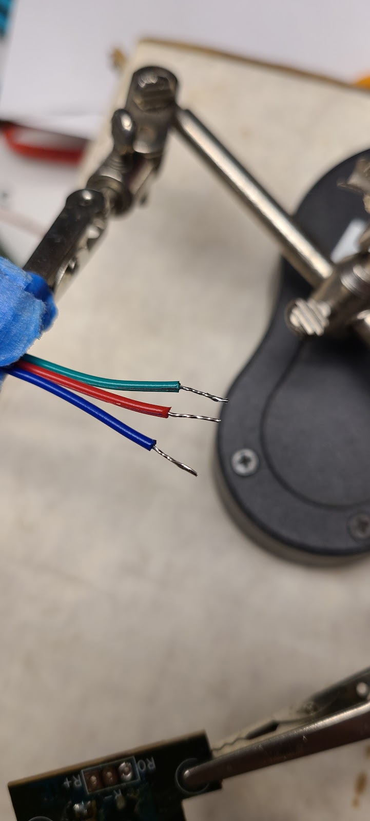

 (Insert ribbon wires through holes, solder to pads, trim afterward)


 A dollop of hot glue would have been good at this point, but I didn't do that.

Then, I butt-welded those to the original wires after cleaning them up, and closed up with heat-shrink.  
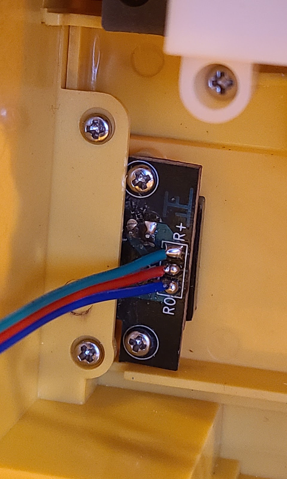


This gave a lot more play to the wire, so I taped things in place to avoid further metal fatigue.

He works!

After all that, WALL-E is mostly working again, finally!   His right-side tread moves better than the left side.

Overall findings

 Overall, this has been a very interesting foray into the world of a vintage WALL-E toy.

 From a quality and build perspective

  • It's great that the toy is mostly repairable
  • The way they managed the motors and expressiveness in the eyes and arms and head is great.
  • The use of triangle-shaped security screws is almost a joke.
  • There are lots of places inside where extra wire would have reduced strain during repair.
  • There are at least two places where the original build used clear, cellophane tape to hold wires in place and thereby prevent strain: the battery pack power lines, and another place where wire bundles were taped together.
  • In many cases, the original soldering  was functional, but didn't stand the test of time, and certainly didn't survive my manipulation.  It was far too easy to break the wire-solder connection points.  Granted, it's probably a 22-year-old toy now.  In many cases, the wires were soldered to pads, and a rubber glue was added.
  • The gearbox assembly -- oh, it would have been much better if they could have had the screws go in from the other side.
  • The press-fit axle-to-gear connection is susceptible to damage, especially if you turn the wheels manually (NEVER do that!)
  • The pin connection on the sides -- the one that holds the tread assembly in place -- also forces you to bend the tread assembly a bit during assembly, and makes it so that repairing the gears can cause damage to the gears.  It would have been nice if the one stabilizing pin (on each side) that matters most could have been made removable from the outside (but perhaps they had to be super careful about potentially having kids swallow small parts that might come loose).
End IR mapping/analysis
For this U-Command WALL-E, do a 44 kHz Raw send of IR pulses using +6000/-2000 lead-in, code 1010, and then a data byte transmitted twice, followed by a +2000 lead-out.  Each 1 bit is +1500/-500, and each 0 bit is +500/-1500.
 
Looking at the sets of codes, I suspect the code names and values match across data sets.  I just have to figure out the extra codes df (makes an air brake hissing sound) and possibly c8.
 

 Next: building a replacement remote control


Thursday, February 20, 2025

TI-84 Plus battery cover

If you're like me, you sometimes get something nice when thrifting, only it's missing its battery cover.

That happened recently when I got a TI-84 Plus graphing calculator.  These are the kind that many high school kids are pushed to buy.  It was in really good condition.  It had its overall cover, and didn't have scratches on the LCD screen.  There wasn't even any battery corrosion on the terminals (which is kind of standard for things you get when thrifting).

But, it was missing its battery cover. 

I went to Thingiverse to see if I could print one, and spent a chunk of time and plastic doing so.  However, it didn't really fit correctly.  Perhaps it was for the TI-84, not the Plus.  Furthermore, it wasn't really a good design for printing, because you'd have to print it sideways.  Printing it flat, which is the fast way to do it, would result in having layers under stress.

And, sure enough, after printing it and trying to get it to fit, I broke off one of the two pins, and the latching mechanism.

Instead, I decided to try to laser cut something for it.  After much trial and error, I found that a good final combination would be a laser-cut cover, laser-cut hinge pins, and a 3d-printed latch.

Here's the calculator in all its glory.


 Lacking the original battery cover, but having the 3d-printed plastic, I did some measurements and was pleased to find that the cover's thickness was close to the thickness of my Michael's basswood pieces (1.8 to 1.9mm).  In the end, the basswood cover doesn't protrude much at all.

I got basic X-Y dimensions for the cover from the 3d-printed piece.  I put the calculator on the flatbed scanner to figure out the curvature at its hinge end, and designed it in Fusion, and exported the shape to SVG.

I then put in some notches for hinge ells.  The notches were made intentionally around 1.65mm.  That way, I could design the hinge pieces so they'd fit snugly.  The flatbed-scanned image made it possible to see where the holes were, and how big they were.

On the latch end, I tried various designs, but ended up making a notch to hold the 3d-printed latch.  I did experiment along the way, and found that Loctite Super Glue (CA) actually bonds PET-G well to the basswood.  But I chose to use a latch design that would wrap around the edge of the notch.


 This is what the profile of the hinges looks like.  It's teeny when laser cut, but holds on well once it's all glued.  I made extras in case any didn't cut properly or got lost.


This is what the latch looks like.  One one side, there's a 1.8mm gap (larger, actually, to account for shrinkage) that holds to the notch area.  The other side has a 1.5mm gap where the latch clicks onto the calculator frame.


Here is a closer view of the hinge pins, glued to the cover.


 And here is a picture of the ugly, 3d-printed latch.  I don't have my settings right for printing this well, but it worked out ok.  I printed it vertically, meaning that the curvy profile sits flat on the print bed, and it rises up 18mm or so.  I used PET-G to print it for flexibility, and used a 2.0mm brim to keep it steady.

I haven't glued it at all in this picture.  It's just friction-/compression-fit onto the wood.


 And here's the end result.  The panel snicks onto the back properly with a satisfying click.  It took about a dozen to get this right, with most of those going to re-prints of the hinge, since it's really hard to take any measurements for it.  I also had a warpy piece of basswood near the end of the project, so I just laser-cut a new one after checking to make sure the wood was mostly flat.


 (Side view to show how it doesn't protrude from the calculator bottom.)

Eventually, I'll probably push the related files to Thingiverse.
 

Tuesday, June 11, 2024

Resizing a 400x400 honeycomb bed to 400x300

Resizing a 400x400 honeycomb bed to 400x300

I got my Full Spectrum Laser hobby laser used, and unfortunately, it did not include its honeycomb laser bed.

I ordered a small one initially, because it was on sale, even though it was small.  Overall, it measured 295 mm x 295mm, though it had markings in the middle that range 0 to 250.

The enclosure of my laser allowed for a honeycomb about 400mm wide (X axis).  Depth (Y axis) could fit quite a bit, but the gantry takes up a lot of it.  And using the too-small bed as an example, it seemed reasonable to target about 300mm depth for the new bed.

It's surprisingly difficult to find a 400mm x 300mm honeycomb bed these days.  Most, it seems, are geared towards diode lasers, which are 400mm x 400mm.

Prices are coming down quite a bit, too.  I saw one person wanting to sell her used, cruddy honeycomb for $80, but I could buy one new on Amazon for $18.99 (with "free" shipping).

I bought one of those 400x400 beds, and got it in a few days.


The bed I got did not have measurement markings on it, like the 295x295 did.  But overall, it was constructed in a similar manner.  There were four edge pieces, which appeared to be extruded aluminum.  Those were connected somehow using rivets, two on each corner.  The honeycomb itself appeared to be strips of corrugated steel, and there were rods going through them.

Naming, labeling, analyzing


I named the frame pieces Top (1), Left (2), Right(3), and Bottom(4).  The corrugated strips run parallel to Top and Bottom.  The internal rods run up and down, parallel to the Left and Right frame pieces.

Remove six of the rivets

My first investigative task was to drill out a few of the rivets.   I just used a hand-held power drill and a strong-looking bit.  After some amount of chipping out, the last thin ring of metal breaks off with a satisfying click.  I ended up removing the two rivets for each of the Top, Left and Right frame pieces.


A look under the covers

Once I had the rivets off, I could wiggle the top frame edge off.  This then revealed what was going on under the covers.


As it turns out, the honeycomb is quite simply and somewhat accurately built.

The four frame edge pieces are indeed extruded aluminum.  In my case, it appears they're anodized, so they are black on the outside.  They're like square tube, missing one side.

The frame edges are cut at a 45 degree angle at each corner.

The edges are joined using steel L corner brackets.  They're strenghtened by a little crimp to keep them from bending under force.  The rivets held the L brackets and frame pieces tightly.  This is one of the corner brackets taken from a top corner, and before I'd removed the rivet backing.


The width of the corner brackets, and the width of each corrugated steel strip, are quite close in size to the width of each frame piece channel.

Remove the frame side pieces

This picture shows the side and top removed.  Note the rod at the top.


Under the top frame piece, welded across all four vertical 4mm rods, there is a 3mm rod.  While this was butted up against the topmost corrugated strip, it wasn't attached to the strips.  It was just holding the vertical rods in place, and kept a little pressure on the corrugated strips.

Having the top and bottom bars welded like this would keep the whole assembly from twisting, too.  And I suppose it would make the top more rigid.  But really, I think that having tight tolerances in the strip widths and the corner bracket width, with respect to the frame channels, keeeps things from moving too much anyway.  So, I didn't see there to be a great need to re-weld the rods later.

Check for square

At some point, I held the Top, Left, and Right pieces up to each other, and was really surprised to find that they were not all the same length!  I think that was a manufacturing flaw originally, and I just didn't notice it.  (For the picture below, the bottom edges of all three frame pieces are resting on flat ground.)


Detach the top rod

I used a Dremel with a cutting wheel and cut down through the existing weld.  Remember to use proper eye and breathing protection when cutting!  Once in far enough, I could use a flathead screwdriver to break the rods apart without too much effort. 


Clean up the weld points on the top rod

I had taken off the top rod in order to remove excess corrugated strips.

I used the Dremel again, this time to grinding away the remaining weld on each vertical rod.  Remember to use proper eye and breathing protection when cutting!  

This left some material on the rod.  I tried to slide strips up and off, but they would get hung up on remaining weld material.

To get things round and smooth again, I stuck a little piece of sandpaper inside my handheld drill, and spun the sandpaper around the weld point until smooth.  I'd then tighten the collet and repeat until satisfied. 


Remove the strips


I lifted many of the corrugated strips up along the four rods, and off.  (If the rod weld points aren't clean enough, you'll know when you try to do this step.)

I stacked the strips as I was going.  It's best if you flip every other one so that all the lengths match and the holes line up. 

I didn't know how many I would be removing, so I just kept going until I had about 11.75" remaining (measured from outer bottom frame edge to top strip).

The following picture shows the honeycomb with many strips removed, and long rods accessible.


Measure, mark, and cut the four vertical rods

(Prior to this step, if you want to practice using a die to thread the rod, you can.)

This part was tricky.  If you don't take the whole thing apart -- that is, if you leave the bottom rod welded -- then it's hard to measure and make all four rods the same length.  I took a "close enough" approach here.  

The 4mm rods were spaced about 95mm apart.  I had a 1/2" plywood board with holes in it already, so I could press that down each rod to the point where the honeycomb strips were tensioned, and then draw marks.  To get this right, I took off more strips (to account for the 1/2" of plywood) and then put those back later.


When done, I eyeball-checked the alignment of the four marks (one on each rod).  In the picture above, I had marks in Sharpie that were incorrect.  The right target is the scratched point closer to the honeycomb.

For cutting the rods, it was easiest to start by using bolt cutters to cut close to the real cut point.  That left room for the Dremel to get closer.

I used the Dremel cutting wheel again to get through most of the way, and then cut with flush cutters at the very end.  Remember to use proper eye and breathing protection when cutting! 


After cutting, I used the Dremel again.  This time, I was trying to chamfer the top, cut edge of each rod.  This would make it safer and also it would make it easier to die-cut threads onto the rod ends.

Use a die to make screw threads at the top of the vertical rods

This was a handheld operation, but it worked pretty well.  (I practiced on the longer rods before step 5).  I wasn't sure what thread to use, but just tried different dies until one fit.  As it turned out to be a #10-24, I felt comfortable using it.  I cut the thread about 1/2" down on each rod.

For this step, I removed more strips temporarily.

One problem I faced was that my tap/die set has a die with arms that are pretty long.  They provide leverage, but in this project they would hit the neighboring rod on each half turn.  I ended up starting each thread with the leverage arms in place, and then removed the arms and continued cutting as I got further down.  

This picture shows the rods now with threads.  Extra strips have been removed so that I could have room to work.

Then I put the temporarily removed strips back.


Use a nut to hold the strips in place, rather than welding a top rod.

I didn't have #10-24 nuts immediately available, so I drew some up in Autodesk Fusion, complete with modeled threads.  I printed those in PETG and they worked straight away.  Each rod got one.

Chop the left and right side pieces to the new length

I put the top frame piece back on, kind of as a dry fit.  This allowed me to get a rough measurement for cutting the Left and Right side pieces down.

I also tested the springiness of the assembly, and I figured I had a 1/2"  of travel, so I could afford to be a little imprecise in my measurement.  The main thing was to ensure that the Left and Right sides (A) had near-perfect 45 degree cuts, and (B) were exactly the same length with respect to each other.

To do that, I lined up both pieces, and stuck them together with blue tape.

I used my chop saw to do the actual cutting.  I used its bevel mechanism, tipping the whole blade over to 45 degrees, and used a separate measuring tool to ensure it was really close to 45 degrees.  Then, I did a first test cut, partly to make sure the blade was up to the task, and partly to get a feel for the cut.  Finally, I marked the cut points, and cut the pieces.

Nobody was injured.  The pieces looked really good.  At this point, I also used some sandpaper to smooth out any sharp edges resulting from the cuts.

Tap the L brackets

The L bracket holes were slightly under 4mm, and so it seemed doable to use #10-24 threads for them now.  I realized around this point that I really had to drill out the Bottom piece rivets, and at least loosen the Bottom piece in order to remove the bottom two L brackets.

I then cleaned off all the remaining rivet material from all L brackets.  This was best done by using a flush cutter to chop off the small, outward protrusion.  Then, I used pliers to pull out the large, inner piece at each hole.

Once that was all done, I used a #10-24 tap on a non-powered drill press to thread the holes.  By this point, I had spent $1.48 for a packet containing ten #10-24 x 1/2" pan-head screws.  Each came with a nut.  I tested each threaded hole as I went, using a #10-24 screw, to make sure I wouldn't be surprised during assembly.

Widen the holes in the frame pieces

Because I was using #10-24 screws, the existing holes in frame pieces had to be widened.  I used a #13 drill but could have gone a little wider.  The idea here is that you don't want the screw to be threading into the frame hole.  Ideally, the screw should slide freely through the frame hole, and catch on the L bracket thread.  In practice, the #13 hole size still was a bit too small, but it ended up being something I could force.

To do this, I finally gave in and removed the Bottom frame piece.

Partially reassemble Top and Bottom

I reattached the L brackets to the holes of the Top and Bottom frame pieces.  That's easiest to do when they're removed from the honeycomb.  Then, I slid each Top/Bottom frame assembly back in place.

The Top and Bottom pieces slide pretty easily back over the corrugated strips at top and bottom.  The side reassembly is harder, just because of how the corrugated strip ends can get offset, and even the slightest change in them can cause the edges to catch on the frame piece.

(In this picture, you also can see the pile of strips that were removed prior to this point.)

Make new holes in the chopped-down side pieces

At this point, the Left and Right pieces were chopped down, leaving the bottom section with its original hole, and the top section of each missing its hole.

I had two chopped-off ends, though, and they served as guides/jigs for determining placement of the new holes.  I lined up the chopped-off piece with each Left or Right piece, stuck them together with blue tape.


I went to the drill press and drilled a #13 hole exactly where a hole would have been.  

Assemble and align

Now I had the Right and Left frame pieces chopped and drilled, so all that was left to do was reassembly.  Or so I thought.

Getting the Left and Right frame pieces back over the full set of corrugate strip ends is difficult, but there is a technique that can be used to make it easier.  It involves hooking the Frame edge piece over one side of all the strips, and then  having an extra straightedge that aligns the strip edges. 

After each of Right/Left frame piece was back in place, I simply connected the #10-24 screws through the frame to the L bracket at each end.

At this step, it helps sometimes to loosen the L bracket's other screw, and then tighten them judiciously.  Overtightening one side can cause the ends to become misaligned, resulting in a bad corner and an exposed, sharp edge.

This is one corner with screws in place.


At this point, the whole honeycomb was back together again!


 At this point, I also zip-tied together all the extra strips.  Only one was kind of scuffed up -- the topmost one, due to how I broke the top rod welds -- but the rest are in good shape.  It looks like I ended up removing 25 of them to bring the honeycomb size down by about 100mm.


Measuring them, I'm getting about .33mm thickness, both measuring individually and averaged over a compressed stack.  They're nearly exactly 20mm wide.  Similar in flat, not yet crinkled, appears to be available online, e.g., this link on aliexpress (1000mm 301 stainless for $4.46?  That would be prohibitively expensive for this kind of build!).

Installation - fail

As a final step, I tried putting the new honeycomb into the FSL hobby laser, only to find that it wouldn't fit!  That's because the pan heads of my #10-24 screws were standing proud of the frame piece, much moreso than the original rivet heads did.

Flattened screw heads

I got out my bench grinder and ground much of each screw head away.  I didn't do this with any particular precision in mind.  I just wanted some of the material to go away.

This is what a ground-down screw head ended up looking like.  This is one of the better looking ones.  Other ones were quite unevenly ground.  They might be harder to undo at this point, but I suppose there shouldn't really be a need to undo these very often, if at all.


With that, the new honeycomb could fit in the laser bed.


 Conclusion

It's totally doable to take a cheap laser honeycomb bed and cut it down to size.  For me the material cost was about

$20 for the 400mm x 400mm bed

$1.48 for the #10-24 screws and nuts

Some nominal filament cost for the 3d-printed #10-24 "nuts" that I made. 

One crappy #10-24 tap that was made from some metal that wasn't as strong as the L bracket metal. :(

It took me quite a bit of time to do this project, but in part that was due to nervousness, never having done it before.  Having done it once, I could probably do one of these in a few hours.

Things to do better next time

I think I would have a better design for my 3d-printed nuts.

I might consider unwelding the bottom rod.  Since there's so much excess rod material, I could chop off the ends of the rods rather than clean the welding material off.  And, having all four of the 4mm rods free would allow me to (A) make sure they're of uniform length, and (B) die-cut threads on their ends more easily.

In retrospect, I could have laser-etched measurement markings on the frame pieces.  That would have happened prior to any reassembly.  I suppose I could still do that.  One of the beautiful things about this project is that I can disassemble and reassemble the honeycomb now.


Tuesday, June 4, 2024

Full Spectrum hobby laser

 Full Spectrum Laser Hobby laser - alignment

I'm posting this after getting very far into reviving an old Full Spectrum Laser hobby laser.  It's 4th gen, I think.

In short, the machine was in rough shape when I got it, which also explains why I got it for a relatively low price.  Among other things, it had problems with its power port, input air line, and front panel switches.  It had good water cooling tubes, but no chiller.  The inside light wasn't working.  The locks were missing keys, but luckily they were all in an unlocked position.  There was no honeycomb.  It had no air exhaust pump and its rear panel for the air exhaust was missing, so there was just an odd, rectangular hole in back.

Most everything else turned out to be working well.  The interlock switches on the front and rear panels were good.  The power supply was good.  The driver board was working.  And, of course, the CO2 tube itself was still working.  I couldn't test any of this when I bought it, so I consider myself lucky.  I also found inside the "Ruler" for doing Z height focusing.

Texting, texting

My first test of the laser -- with safety glasses on! -- was to fire the laser using the "Text" button on the power supply.  Yes, it says "Text", not "Test".  That gave me confidence that the tube itself was operational.  I only did that after having thoroughly cleaned a fountain pump that I'd gotten at a thrift store, and set up a Homer bucket for cooling.

From a power standpoint, I run the laser, water pump, exhaust air pump, and nozzle air pump all off of the same power strip.  The water pump and exhaust pumps are not switched, so when the power strip is turned on, they come on immediately.  This is done for safe operating reasons.  The way it's set up, I can't fire the laser without the water turned on.  (And the gurgling of the pump reminds me to check to make sure it's ok before turning on laser power.)

Pushin' my buttons

While the initial test dot fired using the Text button, the front panel buttons for testing the laser did not work.  Eventually, I found that the old front panel switches were broken and weren't trustworthy.  The Laser enable latching switch, in fact, popped its back off when I depressed it, breaking the switch entirely.  (BTW, one thing I really don't like about this machine's design is that if something breaks and falls into the power area, there's a decent chance that parts will fall into the power supply fan cage.)

I bought a two set of 12mm / 0.5 inch push button switches -- some momentary, some latching -- de-soldered and removed all five old switches, and put in the new ones.

Along the way, I found that the Laser enable switch is set up in series with the door interlocks.  Also, the two laser test buttons are wired in series, which explains why the front panel says you have to press both to test-fire the laser.

The front panel's current control (precision pot) was wired to a three-pin header on the power supply.  There also was a dangling, single-wire connector coming from the control board, and it sure looked like it should go to the current control, but I left that alone.

Software, test cuts, and FSL to the rescue

I got great support help from Full Spectrum Laser, even though the machine is out of warranty.  They were most excellent to work with.  The machine is kind of a predecessor to the popular K40 machines of today, but its driver board is specifically for use with FSL's Retina Engrave software.  After some searching, I found a version I could use.  But it didn't really work.

It turns out that you have to get a specific version of the software to run a machine as old as mine.  Yes, you can get the old Retina Engrave if you look around a bit on their site, but you have to get the right version for this generation of the hobby laser.

Once they steered me to the right version, things were much happier!  I could start Retina Engrave on my laptop, connect to USB, and it would connect.  (If that didn't work, I was probably going to have to head down the path of getting a K40 control board and LightBurn.)  I could get it to test fire from the software.

I did some test cuts.  While I could get some things to burn, I noticed charring on the wiring of the red-dot aiming LED while I was doing some etching tests.  Yikes!

I powered things off and left the machine alone for a while, realizing I'd need to go through the alignment process.

It took some time -- really mostly to get up the nerve to do it -- but I eventually watched the YouTubes and went through the alignment steps.  The first mirror was very poorly set up.  Once it was in place, amazingly, I didn't need to do anything to the second mirror or third mirror.  But until the first mirror was fixed, I definitely could see that the laser was aiming at the back side of the cylindrical third mirror mount, and so it was probably bouncing off and into the wiring.

Prototyping the cow

I'm adding a piece to the FSL here as a test, seeing if this approach might later work on a friend's K40.  His laser has been aligned from mirrors 1 to 2, and 2 to 3.  But nothing is coming out the output tube.

Hence, the cow.  Here is the cow, designed and rendered Fusion.


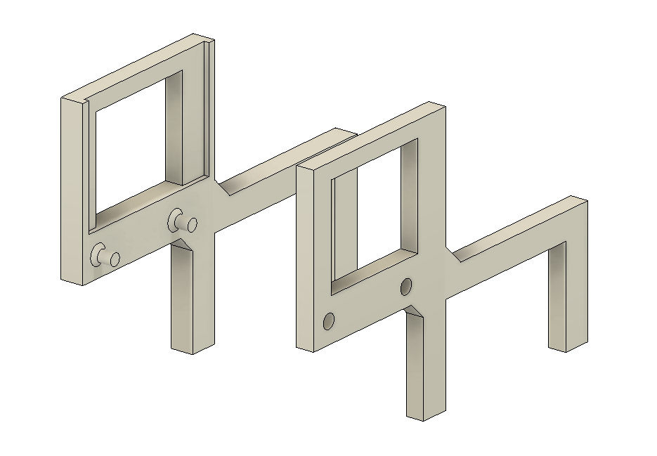
The cow is basically a target holder.  It sits on the gantry in a somewhat predictable and precise way (yes, "somewhat precise"), and is meant to hold a piece of paper.  I don't have the original schematics/dimensions, and don't want to disassemble what's working.  So, I made the cow to help determine where the laser is actually hitting, relative to the gantry bar.

I built the cow with the intent of 3d-printing it.  Since 3d printing has its quirks with respect to dimensional accuracy and shrinkage, I made its legs wider than the bar depth (distance in Y) intentionally, thinking that I would shim it or drill a screw to get it to hold onto the gantry snugly.

The design splits the cow in two.  I used a few printed pins and holes to line up the parts.  I used 1mm chamfers to strengthen the joints where the pins met the left part of the cow.  

I subtracted the left side from the right side to create holes, and then widened those by an extra 0.3mm to allow for shrinkage.  Doing it as two halves made it easier to print flat, and helped avoid problems with supports.  Note that the "left" side of the cow has a rectangular area cut out.  That's there so a piece of target paper can slide in from the top after the two halves are joined.


In real life, I printed the cow using white PETG with 0.2mm layers.  The pegs had some extra gunk when done printing, but I could clean them up with flush cutters.  The two pieces could be joined after that with a satisfying squeeze.  I didn't bother to glue them.

This is what the cow ended up looking like, printed and joined.

Printed cow, PETG, 2 sides joined

As mentioned before, I made the legs of the cow intentionally wider than the gantry bar.  I chose to do that rather than spend time on a test print and making it totally accurate.  What would have been a big waste would have been making the legs too close together, and unable to fit over the gantry.

I found a random magnet that worked well as a shim, and that allowed the cow to fit snugly.

Random sheet magnet as a shim

 These are back and front views of the cow, mounted with shim on the gantry.

Rear view with shim in place (friction fit, not magnetically attached)

 
Front view, mounted on gantry


I cut out, very crudely, some 40mm-wide pieces of paper to act as a first target.


This is what the paper looked like in the head of the cow.


Time for an initial test fire!  Power dial 3 turns, quick hit on the test buttons, and, poof, we have a hole.


The next step was to build some actual targets.  I used Inkscape and threw together a page with 40 mm x 40 mm grids, with lines spaced 4mm apart.

The following are mountings and test firings.

Grid target 2, and grid hole 2:


Grid target 3, and grid hole 3:


Here are holes 2 (lower) and 3 (upper) for comparison.

In both cases, the target grid was flush against the left side of the mount.  With a little magic help from Adobe Photoshop Elements, I clipped out the Target 2 result above, positioned it, de-tombstoned it, etc.

End result from target measurements

The bottom grid line is at pix 834.  Next grid lines up are 756 and 678, meaning the photo is showing 78 pixels per 4 mm.  The hole center is at pix 688, so it's 10 pixels below the grid line.  That means it's about 4mm + (68/78) mm, computing out as (4.872mm) above the bottom.  Also, the hole is pretty much dead on 20 mm from the left edge of the page.

What's Next

Now that I have a pretty good understanding of where the hole is hitting, and because I know the laser is well aligned, I need to make a cat laser pointer that will point through the hole.  Ideally, I'll have a second cow-like mount, placed on the gantry closer to the x=0 point.

If I can make the cat laser's starting point close to same as the hole, shine the laser down along the gantry and through the hole of the target, it should go through to the output mirror and down.

That all should enable us to do 3rd mirror adjustments without actually using the CO2 laser.