Friday, November 29, 2013

Salvaged H-P printer LCD panel (CM160240) on Arduino using Custom Characters

This is a black & white LCD panel that came out of an H-P printer.

I didn't want to mess with it until I knew that the 44780 LCD would work.

It was mounted to a printed circuit board that had momentary contact switches at various points below the buttons.  On one end, there was a thin, flat cable that had something like 26 pins going out of it.  But the cable that came out to the LCD had only 14 lines.
LCD panel with cable
Close-up view of cable
Cable with 0.1-inch proto board for scale
 Since the cable was at 1mm separation, it was too fine for my soldering ability.  That meant that for me to mess around with the LCD, I'd need some way to break out the cable pins so that I'd get back to 0.1" separation.

I took some digging, searching on the wrong term ("ribbon cable") but I eventually found that the cable is referred to as an FPC (flexible printed circuit) or FFC (flat flex cable / flat flexible cable).

It turned out that there was a nice set of breakout boards available at Newhaven (google "Newhaven ffc adapter"), but they were around $10 each, not including shipping.

Instead, it turned out that Jameco had a little piece that fit a 14-pin, 1mm FFC, for only $0.39 each:
http://www.jameco.com/webapp/wcs/stores/servlet/Product_10001_10001_2144876_-1
The datasheet is at http://www.jameco.com/Jameco/Products/ProdDS/2144876.pdf

I got a couple of those -- always get a backup in case the first one fails!  The way it's set up, it has output pins that are in two rows, seven pins each separated at 2mm, and the pins are offset.  The rows themselves are also 2mm apart.  Since I didn't have any means (yet) to build my own PCB and my own breakout board, nor a way to drill holes at 2mm separation, I bent the rows apart to get more work room, and soldered wires to the pins.  Then, I used heatshrink tubing (from Halted, www.halted.com) for insulation.

The top of the breakout board looks like this:

I filed the holes a little larger so that the wires could be pulled through.  Then, I cut the wires to length and soldered them to push-in headers.  The end result was that all the odd-numbered wires ended up on one side, and the even-numbered ones were on the other side.  The back side of the board is here.  The outermost pins of the headers were soldered just for stability.

Of course with my soldering (non-)skills, I had to check all solder joints for proper connectivity, and make sure I didn't accidentally create any solder bridges.

Then I connected the FFC to it, just to double-check and make sure I knew which pins were which.

But which wires were which?

When I first looked at the LCD on its mount, it wasn't clear what chip was behind it, nor which pins would do what.

My first hint was that it had 14 pins.  Thus I hoped it would obey the same rules as the 44780.

The second hint was a closer inspection of the PCB that held the contact switches.  This is a backlit view of the board with pins in the order 1..14 from left to right.
The thing that stood out was that pin 3 had a thicker trace, and I took that to mean it represented Ground.

The flipside of the board is shown here.  It shows that pin 2 is connected via a capacitor (labeled C1) back to pin 3 (ground), suggesting pin 2 was power.  When I put 5V to pin 2 and ground to pin 3, the board showed a row of black squares.


But still, that didn't tell me anything else about the rest of the LCD pins.  The enable, reset, read-write, contract, and data pins could be in any combination.

I removed the LCD from its plastic mounting to get a closer look.  This took some *very* careful prying.  In retrospect, I might have done well to have applied some heat to loosen up the glue that was keeping it stuck on.  One time, when I was removing the panel in this way, I generated enough static with the plastic housing that it cause a few images to light up on the display, and I was afraid I'd fried it.  So be careful.  I'm not sure if heat is even a good idea, as that might loosen the glue, but damage the panel.


I gently removed the inspection sticker that was on top of the PX16214 identifier, and once outside the mounting, I could also see the DATA IMAGE vendor name.  (Earlier, only the word "IMAGE" was visible.)  Note also on the image above that there are three black bars.  Each of those, I think, is simply a piece of standoff foam with adhesive on it, and that's what kept the LCD panel stuck onto the PCB.

That allowed me to google "data image lcd px16214 p184 s-11" which gave me a single, solitary hit:

LCD mit 14 Pins, aber scheinbar keinem HD44780-kompatiblen ...

www.mikrocontroller.net/topic/187292
Thankfully, I'd gotten a bit of German in high school, and that in combination with knowing how to look for some technical terms let me know that I was on the right path.  Google translate then to help.

The page pointed to this first:
http://www.tstonramp.com/~pddwebacc/cdm/CDM-16214.pdf
and the pins for that are the same as for the 44780, but in reverse order.

However, it still didn't agree with my expectation that pin 3 was ground, and pin 2 was Vcc.

Later, though, in the same mikrocontroller.net web page, it referred to
http://www.optologic.ch/data/CHARACTER_DISPLAYS/PDF/CM160240.PDF

On that page, it showed the pin-shifted positioning that I was after:
pin 3 = Vss (0V)
pin 2 = Vdd (+5V)
pin 1 = Vo (LCD Drive Voltage)
and then it loops around to
pin 14 = RS
pin 13 = RW
pin 12 = E
pins 11..4 = DB0..DB7, respectively

I changed my 44780 sketch to initialize with a 16x2 display, and wired everything together, and it worked -- mostly.  For some reason, doing

lcd.setCursor(0,0);
lcd.print("tankdemo");

would only render the "demo" part to the screen.

I don't know why, but I had to offset all setCursor commands by adding 4 in order for things to line up properly.

The other thing I noticed is that there is no separating pixel row between lines 0 and 1 on the screen, but there still is a dead pixel separating each column.

The end result wiring is a bit of a spaghetti mess.


After I got all that together, I modified the code to allow for some variation to the message displayed on line 0, and messed around with the tank image a bit since this black & white LCD would erase pixels much faster than the 44780.

Here's the resulting code.
#include <LiquidCrystal.h>

// According to CM160240.html
// The pins on the salvaged HP printer's 16x2 LCD display might be
// 1 V0
// 2 Vdd +5v
// 3 Vcc GND
// 4..11 are DB7..DB0, respectively
// 12 EN (H, HL Enable signal)
// 13 RW (H read, L write)
// 14 RS (H data, L command)

// The blue 44780 uses
// 1 = gnd
// 2 = Vcc
// 3 = pot 10k-20k for contrast
// 4 = RS
// 5 = RW
// 6 = EN
// 11 = D4
// 12 = D5
// 13 = D6
// 14 = D7
// Ref. http://www.hacktronics.com/Tutorials/arduino-character-lcd-tutorial.html
// and HD44780 wiring pages

// and I'd used
LiquidCrystal lcd(7, 8, 9, 10, 11, 12);
  // RS, EN, DB4, DB5, DB6, DB7
 
// so... I need to wire up pins 14 RS, 12 EN, 7 DB4,6 DB5,5 DB6,4 DB7
// and wire RW to ground
// and consider using 10-20k for contrast on pin 1 (optional?)
// and set 2 to 5v
// and set 3 to 0v
// so ard7 = bd14
//    ard8 = bd12
//    ard9 = bd7
//    ard10 = bd6
//    ard11 = bd5
//    ard12 = bd4
// gnd = bd3
// vcc = bd2
// gnd = RW = bd13


// Board
// 1 = gnd
// 2 = Vcc
// 3 = pot 10k-20k for contrast
// 4 = RS
// 5 = RW
// 6 = EN
// 11 = D4
// 12 = D5
// 13 = D6
// 14 = D7
// Ref. http://www.hacktronics.com/Tutorials/arduino-character-lcd-tutorial.html
// and HD44780 wiring pages

// RW has to be wired low to write, else it remains in "read" mode

byte sprite0[8];
byte sprite1[8];
byte sprite2[8];
byte sprite3[8];

#define XOFFSET 4
#define LCD_CHAR_WIDTH 16
void setup() {
  // set up the LCD's number of columns and rows:
  lcd.begin(LCD_CHAR_WIDTH, 2);
  lcd.setCursor(XOFFSET,1);
  for (int i=0; i<LCD_CHAR_WIDTH; i++) lcd.write('@');
  memset(sprite0,7,8);
  memset(sprite1,7,8);
  memset(sprite2,7,8);
  memset(sprite3,7,8);
  lcd.setCursor(XOFFSET,1);
//  Serial.begin(9600);
}

// Need eight 32-bit quantities that I can use for shifting bits around.
// The original tank image is in these values.

long tankImg[] = {
  ((long)B000000 << 10) | ((long) B000000 << 5) | B000000 // antenna tip zeroed on HP LCD
 ,((long)B010011 << 10) | ((long) B011110 << 5) | B000000 // turret top
 ,((long)B011111 << 10) | ((long) B011111 << 5) | B011110 // turret mid with barrel
 ,((long)B000111 << 10) | ((long) B011110 << 5) | B000000 // turret base
 ,((long)B001111 << 10) | ((long) B011111 << 5) | B010000 // tread top
 ,((long)B010000 << 10) | ((long) B000000 << 5) | B001000
 ,((long)B010000 << 10) | ((long) B000000 << 5) | B001000
 ,((long)B001111 << 10) | ((long) B011111 << 5) | B010000 // tread bottom, 24 pixels total in tread
};

// tankx is the bitwise position across the screen.
// tankcharx is the character-wise position, thus tankx / 5.
// It can be negative.
// At tankx zero, the tank is on the left of the screen
// so tankImg bytes are broken into four custom chars
// the fourth of which being blank bits
// At tankx one, the tank bits shift a bit to the right
// and if I'm clever, the treads are computed so they "rotate"
// And so on
// Because there are five bits horizontally per custom char
// and the tank treads go every other, I can repeat the original
// tank treads starting at even char positions

#define RESTART_X_POS -15

int tankx = RESTART_X_POS;
int tankcharx;
int tankchary = 1;
int treadx = 0;

#define BITS_PER_CHAR 5

void writeAt(int x, int y, byte b)
{
  if (x >= 0 && x < LCD_CHAR_WIDTH) {
    lcd.setCursor(XOFFSET+x,y);
    lcd.write(b);
  }
}

int msgID = 0;
char *msgs[] = {
   "Tank demo!"
  ,"H-P printer LCD"
  ,"CM160240"
  ,"Thanks to the"
  ,"guys in Germany"
  ,"who wrote up the"
  ,"pin assignments!"
//  1234567890123456
};
#define NUM_MSGS 7
long lastMsgTime = 0;

void loop() {
  if (millis() - lastMsgTime > 2000) {
    lastMsgTime = millis();
    int j;
   
    lcd.setCursor(XOFFSET,0);
    int blanks = (LCD_CHAR_WIDTH - strlen(msgs[msgID]) )  / 2;
    for (j=0; j<blanks; j++) lcd.write(' ');
    lcd.print(msgs[msgID]);
    for (   ; j < LCD_CHAR_WIDTH; j++) {
      lcd.write(' ');
    }
   
    msgID++;
    if (msgID >= NUM_MSGS) {
      msgID = 0;
    }
  }
 
  tankcharx = tankx / BITS_PER_CHAR;
//  Serial.print("tankx = ");
//  Serial.print(tankx);
//  Serial.print("  tankcharx = ");
//  Serial.println(tankcharx);
 
  // Initial rendition, no rotation of treads
  if ((tankx % BITS_PER_CHAR) == 0) {
    // Full shift is on, need to draw a blank where the tank last was
    writeAt(tankcharx-1, tankchary, ' ');
    // Draw the tank's custom characters
    writeAt(tankcharx,   tankchary, 0);
    writeAt(tankcharx+1, tankchary, 1);
    writeAt(tankcharx+2, tankchary, 2);
    writeAt(tankcharx+3, tankchary, 3);
  }
 
  // Compute the bits of the individual custom chars
  int shiftbits = (tankx % BITS_PER_CHAR);
//  Serial.print("shiftbits = ");
//  Serial.println(shiftbits);
  if (shiftbits < 0) { shiftbits += BITS_PER_CHAR; }
  for (int y=0 ; y<8; y++)
  {
    long lval = tankImg[y];
    switch (treadx) {
      case 0:
        switch (y) {
          case 4:
            lval ^= 0x2cb0; break;
          case 7:
            lval ^= 0x2490; break;
        }
        break;
      case 1:
        switch (y) {
          case 4:
            lval ^= 0x1240; break;
//            lval ^= 0x36d0; break; // This setting has fewer pixels on on top
          case 5:
            lval ^= 0x0008; break;
          case 6:
            lval ^= 0x4000; break;
          case 7:
            lval ^= 0x0920; break;
        }
        break;
      case 2:
        switch (y) {
          case 4:
            lval ^= 0x0920; break;
//            lval ^= 0x1b60; break; // This setting has fewer pixels on on top
          case 5:
            lval ^= 0x4000; break;
          case 6:
            lval ^= 0x0008; break;
          case 7:
            lval ^= 0x1240; break;
        }
        break;
    }
   
    long lshifted = lval << (BITS_PER_CHAR-shiftbits);
    sprite0[y] = (byte)((lshifted >> (3*BITS_PER_CHAR)) & B011111);
    sprite1[y] = (byte)((lshifted >> (2*BITS_PER_CHAR)) & B011111);
    sprite2[y] = (byte)((lshifted >> (1*BITS_PER_CHAR)) & B011111);
    sprite3[y] = (byte)((lshifted >> (0*BITS_PER_CHAR)) & B011111);
  } // end computation of the four custom characters' eight lines
 
  // Update the custom chars.  This causes them to be updated
  // immediately on the LCD screen.  I haven't tried rendering
  // in reverse order to see if that makes for any better or worse
  // animation effect.
  lcd.createChar(0, sprite0);
  lcd.createChar(1, sprite1);
  lcd.createChar(2, sprite2);
  lcd.createChar(3, sprite3);
 
  // Move the tank to the next position and reset to the left off screen
  // if it goes far enough off to the right.  Also keep the "tread"
  // offset ticking.
  ++tankx;
  if (tankx >= 5*LCD_CHAR_WIDTH+5) { tankx = RESTART_X_POS; }
 
  ++treadx;
  if (treadx == 3) { treadx = 0; }
 
  // A short delay before we move the tank again.
  // Slower delay = less blur, given the 44780 I have
  // is slow to erase the lit-up pixels.  I like delay(100) milliseconds.
  delay(100);
}


And hopefully blogspot will allow me to post a video here... cross yer fingers...


Thursday, November 28, 2013

LCD Panel (RT0802B-1, 44780) on Arduino using Custom Characters

My latest project has been to figure out how to interface an LCD with an Arduino Uno.  I was inspired to do this, because someone had left their LCD project in a parts bin at the Tech Shop in Menlo Park.  In fact, the board I got had an Arduino Mini Pro on it, along with the LCD panel and some other components, so that will be saved for some future project.

The board I got was fairly awfully wired and soldered.  All the wires were blue, and many of the solder joints fell apart as I handled it.  Originally, I thought I'd get the Arduino working and powered, but I ended up just cutting the leads to the LED panel and rewiring it.

The LED panel is the normal 8x2 display that most hobbyists use.  There are tons of pages out there that describe the pins, and the LiquidCrystal library works fine.

First, the panel.  This is a 14-pin LED with twelve pins marked on the left side, and two marked A and K.  This is the top view:
 and the bottom view:

On the back side you can see that the pins are marked 1,2 at the bottom and 13,14 at the top.  On the left, you see the RA and RK markings, which correspond to Anode and Cathode, respectively.

In addition, there's the RT0802B-1 VER2.0 designation on the back, which follows a 44780 pinout.

When I first got this on its original board, it was a tangled mess of wires.  So after taking it apart and cutting wires to a more manageable and consistent length, I wired them to a header that would be more prototype-compatible.  (The wires themselves were of a gauge that is too thin to hold properly in a solderless breadboard, too.)  Now I have a board that I can plug wires into, and the wires are in the order 1..14, RA, RK.

The first time I built this, I totally blew the wire ordering.  I got 1,2 set up properly, which is good because they represent ground and Vcc, but from then on, I swapped pairs, so 3,4 became 4,3 on the headers and so on.  The unit would show a bunch of squares, because it was getting power properly, but the rest of the system naturally would not work at all.  The basic lesson here is: don't use the same wire color for everything!  (Why are they still all blue?  I got it this way, and didn't want to risk damaging it by un-soldering and re-soldering.)

The next step was basic breadboarding, following examples online.  Here's the wired-up result:
(In the image above, you can see I had a mistake in the wiring of the power to the contrast resistor, but it worked anyway in this configuration.)

Following the wires, it ends up with
LCD1 = GND
LCD2 = Vcc
LCD3 = Contrast voltage
LCD4 = RS (reset), orange, Ard 7
LCD5 = RW (read/write, tied to ground)
LCD6 = EN (enable), yellow, Ard 8
LCD7 = DB4 (data 4), blue, Ard 9
LCD8 = DB5 (data 5), orange, Ard 10
LCD9 = DB6 (data 6), white, Ard 11
LCD10 = DB7 (data 7), yellow, Ard 12
LCD11,12,13,14 = floating
LCD RA = anode = Vcc
LCD RK = cathode = Ground

The sketch code would then simply import the LiquidCrystal library and set up the LCD object as:

LiquidCrystal lcd(7, 8, 9, 10, 11, 12);
  // RS, EN, DB4, DB5, DB6, DB7


From there, the basic sketch code worked.  I built a few other quick sketches that would scroll Jabberwocky across and up the screen.  I found that this LCD has a slow fade, so if you do something like text scrolling, you have to slow it down a lot (longer delay() calls between redraws).

Custom characters for an LCD


After that, I started messing with the custom character function.  The 44780 (as all these sites will tell you) allows you to store eight characters' worth of special images where you get to specify the 5x8 bit pattern.  For example, code like this would set up a special character in slot 1, set up some funky bits for it, and draw it in column 0 (first column), line 0 (first line) of the LCD.
#include <LiquidCrystal.h>


LiquidCrystal lcd(7, 8, 9, 10, 11, 12);
  // RS, EN, DB4, DB5, DB6, DB7


byte bits[] = {
  B00000
, B00100
, B01010
, B10001
, B11111
, B10001
, B01010
, B00100
};

void setup() {
  lcd.begin(8,2); // n chars wide, m lines high
  lcd.setCursor(0,0);
  lcd.createChar(1, bits);
  lcd.write((byte)1);
}

void loop() {
}


One thing that's funny is that the LiquidCrystal example code on the Arduino web site declares a byte array of eight bytes, but only specifies seven of them.

LCD Sprites

I found that assigning new values to a custom character's definition causes immediate screen updates, wherever that character already exists on the screen.  You could use the code above and draw eight of the same custom character on the screen (repeat this line eight times)
  lcd.write((byte)1);

but after that, you can change the bits of the custom character, and it'll cause all eight characters to change at once.  So, you can change what's inside the bits[] byte array, and repeatedly call lcd.createChar(1, bits), and cause some form of animation to occur.

So I updated my sketch to do that, just making a basic marquee line.  It would set a few of the bits on three of the lines, and then shift them around after a short delay.

Gutters

If you look at your LCD under magnification, you'll probably find that the bits of each character are not adjacent to each other.  For my RT0802B LCD, there's about (maybe precisely?) one pixel separation vertically and horizontally between lines and characters, respectively.

Tank

I took it upon myself, then, to write some code that would take advantage of the custom characters and the ability to update them in-place.  I chose to draw a little tank, similar to what I'd seen in ye olde tymes when playing Rescue Raiders!

Basically, I drew a tank on some graph paper, assuming I'd eat up three custom characters with it.  I'd shift it over a bit at a time until I'd shifted four times, after which I could repeat.  Since I'd be shifting bits out of the third custom character to a fourth position, I'd really end up using four custom characters.

Here's the original sketch on graph paper.


The code defines the tank using eight long integers, each providing more than enough room for the twenty bits that I'd really be using for four characters.

For the main loop, I'd have a tank "x" position in pixels.  I could then just take a modulo 5 of that value to find out how many bits I'd have to shift the image around.  Then, I split the 20-bit long ints into individual bytes, masked off the upper three bits (logical AND the value with B011111) and after assembling all four sets of eight bytes, I'd push the values into the LCD's custom character memory.

I'd also divide the tank x position by 5 to figure out which character location I'd draw at.  To avoid leaving trailing bits around, I'd wipe out the space to the left with a whitespace character, then draw custom chars 0, 1, 2, and 3.  Anything to the right would just get overwritten as the tank would move.

In action


Sorry for the sideways video!  Here you can see the tank moving along and see how the fade speed of pixels affects the result.


As the code evolved, I messed with the delay between loops and the imagery of the tank (initial version had every-other treads, but later revs had an on-on-off pattern for a better look).

What's next

After messing with the 44780, I went on to working on an LCD panel that I salvaged from an old H-P printer that I got via Freecycle.

The code

The resulting code is below.

Note: even though there's the gutter "pixel" to deal with, I left the code using 5 as the modulo value.  I could move it to 6 in various places in the code, and that would make it look like the tank was moving behind some kinds of bars, but I tried that and it messed up the treading presentation too much.

To do: I think I need to put some Arduino license attribution in here somewhere...

#include <LiquidCrystal.h>

LiquidCrystal lcd(7, 8, 9, 10, 11, 12);
  // RS, EN, DB4, DB5, DB6, DB7

// Board
// 1 = gnd
// 2 = Vcc
// 3 = pot 10k-20k for contrast
// 4 = RS
// 5 = RW
// 6 = EN
// 11 = D4
// 12 = D5
// 13 = D6
// 14 = D7
// Ref. http://www.hacktronics.com/Tutorials/arduino-character-lcd-tutorial.html
// and HD44780 wiring pages

// RW has to be wired low to write, else it remains in "read" mode

byte sprite0[8];
byte sprite1[8];
byte sprite2[8];
byte sprite3[8];


void setup() {
  // set up the LCD's number of columns and rows:
  lcd.begin(8, 2);
  lcd.setCursor(0,0);
  lcd.print("tankdemo");
  lcd.setCursor(0,1);
  lcd.print("@@@@@@@@");
  memset(sprite0,7,8);
  memset(sprite1,7,8);
  memset(sprite2,7,8);
  memset(sprite3,7,8);
  lcd.setCursor(0,1);
//  Serial.begin(9600);
}

// Need eight 32-bit quantities that I can use for shifting bits around.
// The original tank image is in these values.

long tankImg[] = {
  ((long)B010000 << 10) | ((long) B000000 << 5) | B000000 // antenna tip
 ,((long)B010111 << 10) | ((long) B011110 << 5) | B000000 // turret top
 ,((long)B001111 << 10) | ((long) B011111 << 5) | B011110 // turret mid with barrel
 ,((long)B000111 << 10) | ((long) B011110 << 5) | B000000 // turret base
 ,((long)B001111 << 10) | ((long) B011111 << 5) | B010000 // tread top
 ,((long)B010000 << 10) | ((long) B000000 << 5) | B001000
 ,((long)B010000 << 10) | ((long) B000000 << 5) | B001000
 ,((long)B001111 << 10) | ((long) B011111 << 5) | B010000 // tread bottom, 24 pixels total in tread
};

// tankx is the bitwise position across the screen.
// tankcharx is the character-wise position, thus tankx / 5.
// It can be negative.
// At tankx zero, the tank is on the left of the screen
// so tankImg bytes are broken into four custom chars
// the fourth of which being blank bits
// At tankx one, the tank bits shift a bit to the right
// and if I'm clever, the treads are computed so they "rotate"
// And so on
// Because there are five bits horizontally per custom char
// and the tank treads go every other, I can repeat the original
// tank treads starting at even char positions
int tankx = -15;
int tankcharx;
int tankchary = 1;
int treadx = 0;

#define BITS_PER_CHAR 5

void writeAt(int x, int y, byte b)
{
  if (x >= 0 && x <= 7) {
    lcd.setCursor(x,y);
    lcd.write(b);
  }
}

void loop() {
  tankcharx = tankx / BITS_PER_CHAR;
//  Serial.print("tankx = ");
//  Serial.print(tankx);
//  Serial.print("  tankcharx = ");
//  Serial.println(tankcharx);
 
  // Initial rendition, no rotation of treads
  if ((tankx % BITS_PER_CHAR) == 0) {
    // Full shift is on, need to draw a blank where the tank last was
    writeAt(tankcharx-1, tankchary, ' ');
    // Draw the tank's custom characters
    writeAt(tankcharx,   tankchary, 0);
    writeAt(tankcharx+1, tankchary, 1);
    writeAt(tankcharx+2, tankchary, 2);
    writeAt(tankcharx+3, tankchary, 3);
  }
 
  // Compute the bits of the individual custom chars
  int shiftbits = (tankx % BITS_PER_CHAR);
//  Serial.print("shiftbits = ");
//  Serial.println(shiftbits);
  if (shiftbits < 0) { shiftbits += BITS_PER_CHAR; }
  for (int y=0 ; y<8; y++)
  {
    long lval = tankImg[y];
    switch (treadx) {
      case 0:
        switch (y) {
          case 4:
            lval ^= 0x2cb0; break;
          case 7:
            lval ^= 0x2490; break;
        }
        break;
      case 1:
        switch (y) {
          case 4:
            lval ^= 0x1240; break;
//            lval ^= 0x36d0; break; // This setting has fewer pixels on on top
          case 5:
            lval ^= 0x0008; break;
          case 6:
            lval ^= 0x4000; break;
          case 7:
            lval ^= 0x0920; break;
        }
        break;
      case 2:
        switch (y) {
          case 4:
            lval ^= 0x0920; break;
//            lval ^= 0x1b60; break; // This setting has fewer pixels on on top
          case 5:
            lval ^= 0x4000; break;
          case 6:
            lval ^= 0x0008; break;
          case 7:
            lval ^= 0x1240; break;
        }
        break;
    }
   
    long lshifted = lval << (BITS_PER_CHAR-shiftbits);
    sprite0[y] = (byte)((lshifted >> (3*BITS_PER_CHAR)) & B011111);
    sprite1[y] = (byte)((lshifted >> (2*BITS_PER_CHAR)) & B011111);
    sprite2[y] = (byte)((lshifted >> (1*BITS_PER_CHAR)) & B011111);
    sprite3[y] = (byte)((lshifted >> (0*BITS_PER_CHAR)) & B011111);
  } // end computation of the four custom characters' eight lines
 
  // Update the custom chars.  This causes them to be updated
  // immediately on the LCD screen.  I haven't tried rendering
  // in reverse order to see if that makes for any better or worse
  // animation effect.
  lcd.createChar(0, sprite0);
  lcd.createChar(1, sprite1);
  lcd.createChar(2, sprite2);
  lcd.createChar(3, sprite3);
 
  // Move the tank to the next position and reset to the left off screen
  // if it goes far enough off to the right.  Also keep the "tread"
  // offset ticking.
  ++tankx;
  if (tankx >= 45) { tankx = -15; }
 
  ++treadx;
  if (treadx == 3) { treadx = 0; }
 
  // A short delay before we move the tank again.
  // Slower delay = less blur, given the 44780 I have
  // is slow to erase the lit-up pixels.  I like delay(100) milliseconds.
  delay(200);
}


Saturday, November 9, 2013

Light panel from 15" monitor

I'm building a light panel.

I looked at some examples on youtube where people used surface-mounted LED light strips, and am heading down that path.

Materials selection

How do I choose an LED light strip?

The parameters appear to be:
- 3528 vs 5050.  The numbers indicate LED size.  The 3528s are 3.5mm x 2.8mm, whereas the 5050s are 5mm x 5mm.  The 5mm LEDs reportedly emit about 3x the light compared to the 3528s.
- Double density.  You can get 3528s at 300 LEDs / meter, or 600 LEDs / meter.
- Color.  You can get cool white, warm white, pure white, and various colors include RGB combinations.
- Addressable vs. non-addressable.  The addressable ones look really fun, and would allow me to do things like make dot matrix displays, but they're much more expensive.
- Waterproof vs. non-waterproof.

The page I liked best with images showing comparative layouts is at
http://www.ledlightsworld.com/page.html?id=32
but there are tons of sites out there that describe the choices.

Roughly speaking, I'm trying to get a rectangular layout, approximately 30cm wide x 20cm high, and holding about 600 lights.

I ordered a warm white light strip over eBay from someone in Portland.  The listing said it would be a 600 LEDs/m strip, but when I opened it, I only got 300 LEDs/m.  I chose that place over a place in China just to get a faster delivery.  After some complaining, we negotiated a $5 refund, so I ended up with a 300 LEDs/m strip to experiment with.  When I'm done, I intend to take that strip, and put it in the back of my TV so I can get some inexpensive, warm backlighting.  (The seller said they later checked their inventory and would update their listing.)

Width, density, and layout

The strip I got is 8mm wide, which is just as the web site said.  The lights themselves are 3 LEDs every 5cm (therefore 300 total in 5 meters), so laid out in one strip, I'd get a light every 1.66cm, quite a bit less dense than I'd like.

The "single density" 3528 strips allow cut points every 3 lights, or every 5cm. 

The double density strips are still 8mm wide, but put 6 lights every 5 cm.  The images online suggest that they allow cut points every 3 lights, still, so I may be able to cut at the 2.5cm mark.

The 5050s are on a 10mm-wide strip (1cm wide), and still 3 lights per 5cm.

Plain rectangular layout

In a basic layout, I could lay out each strip horizontally.  I'd cut at every sixth cut point (6 x 5cm = 30cm) and so I'd have 18 lights per mini strip, and each mini strip would be 30cm wide.  That would give me 16 strips and some leftovers.

Since I'm trying to lay out vertically into 20cm height, and the strips are 0.8cm wide, I could put about 24 of them in, densely packed.  Having only 16 ministrips, I'm well within the 24 count, and would have to space them out more.  Roughly speaking, I could space them at 1.2cm separation.  The first would be at 0cm, and then 16th would be at (n-1)*1.2 = 18cm origin, and stretch to 18.8cm endpoint.  Or, I could separate them by 1.4cm and stretch to 22.4cm terminus.

Now, with this kind of "rectangular" layout, I'd end up with 16 strips, thus 16 lights x 18 lights total, or 288 lights of the 300 on the whole strip.

If I were to go to a double density setup, I could get double the number of lights, or 576 lights.

If I were to use the 5050s on a 300 LEDs/m strip, my strip width would increase to 1cm.  But, since the layout plan still has the strips laid out every 1.2cm or 1.4cm, the 5050s would fit.

So, using the double-density 3528s would double the light in the same space, and using the 5050s would triple the light in the same space.  The only design point complication is that I'm not really getting 600 lights, and if I use an "egg crate diffuser", it would have to be rectangular or else the diffuser might actually block LEDs here and there.

Diamond layout

Instead of laying out the strips so that lights are directly aligned from top to bottom, I could stagger them, getting a "diamond" layout instead.  Doing this with the single density 3528s or 5050s would work, but it would make as much sense with the double density 3528s.

Power requirements


Each LED strip has different power requirements and capabilities.  The web site listed earlier suggests that I can run them at
SD 3528 = 12V, < 2A, < 24W
DD 3528 = 12V, < 3A, < 36W
SD 5050 = 12V, < 6A, < 72W

I don't quite understand those ratings.  You would think that the DD 3528s should handle double the amperage, and hence could be run at 12V, < 4A, < 48W.  Maybe there's something else in the circuitry that is current- or heat-limited on those strips, or maybe it's particular to a manufacturer's design.

I'm not sure if the LEDs are current-limited or current-hungry.

Power supplies

In my trip to Weird Stuff, I found several power supplies: a 12V, 2A one from Condor, and another 12V, 5A one from Condor.  I didn't find anything that was in the 12V, 3A range, so when my DD 3528s come in, I'll just have to see how they behave with the 2A supply, and look for another supply via eBay.

A cursory scan of eBay puts a 12V, 3A power supply with connectors at $13.99 with free shipping.

Amazon has one for $9.99 with free two-day shipping:
Lighting EVER® Power Adaptor, Transformers, Power Supply For LED Strip, 12V, 3A Max, 36 Watt Max, US Plug

From a physical standpoint, I don't want a massive 12A power supply such as you'd find from an ATX motherboard.  It has to be more like a laptop power supply brick with a 9V-style jack coming out.

I may be able to use a larger power supply and build my own voltage regulator board, but it'd have to handle high wattage.

Dimming

I also want to be able to set the light level of the LEDs, and there are various dimmer switches available.  The most appealing at this point is a dial-based mechanism that uses PWM to control the brightness.  It's rated at 6A max current "per color":
Amazon, $9.99 plus $4.99 shipping: LEDPRO PWM Dimming Controller For LED Lights or Ribbon 3528 5050 strip 12V 8A Dimmer
but similar can be ordered from China for $2 or $3 with just $3 shipping.  China is whoopin' our manufacturing butt, but probably at the cost of pollution.

The dial-based controls are attractive because I want one that doesn't "forget" its setting.  There are wireless models out there, but they might fail, or you might lose the little adjustment fob.  There are also push-button ones out there, but they won't integrate cleanly with the build.  With a dial setting, I could just drill a hole in the back, and screw it on, I think.

The dial-based one is 89x59x35mm (LxWxH).  Example on eBay: LED Light Dimmer Modulator Brightness Adjustable Control 12V~24V 8A #JT1 E0Xc.
It'd be ugly, but I could mount it outside the box just above the stand connection.  At least there it's behind the scenes, and not likely to be bumped.  That one is rated at 8A, too.

A few other alternatives:
12V inline dimmer on eBay, Min LED Single Color Dimmer Amplify PWM for 3528/5050 LED Light/Strip
 That one is only $4 with free shipping, but rated at 5A

eBay: NEW DIGITAL 12V 60 WATT PWM VARIABLE BRIGHTNESS LED DIMMER DRIVER KIT
That one is $11 from Bay City, OR, and requires assembly, but it would totally fit inside the box.

eBay: DC 10A 12V 24V 36V 25Khz Motor Speed Driver Adjuster PWM Control Controller
This one is $8 with $1 shipping from within the US, but the page's English is so mangled, I suspect it's originating from China.
What's really intriguing about that one is that it has a separable potentiometer and small form factor.  I found it when looking for motor speed controllers, not LED dimmers.  But both are PWM, and it appears to meet the electronic requirements.  I'm not sure if it would be noisier or if having constant current is a requirement.

Containing box

While at Weird Stuff, I also looked at options for light diffusion (hoping for a silver egg crate, no luck) and having a container for the panel.  I looked at old child-sized laptops, and they also had several other things.  On one simplest end of the spectrum, there was a plain old frame.  I could mount one of those on top of a containing box, and use the existing glass.  On the other end of the spectrum, there were stacks of old, torn-apart laptops.

Then I noticed the monitors that were on sale.  Most were too large for my needs, but I found a KDS 15" monitor that looked right.  My basic requirements were that it be cheap, and able to be disassembled.

The KDS 15 was on a stand, and had little rubber covers that, I guessed correctly, were simply stuck on top of normal Phillips screws.

One thing to note: as with other electronics hackery, the older and more foreign-made stuff is easier to deal with, most of the time.  I chose this monitor partly because it wasn't something as sleek as a Mac.  I've dealt with removing the cover and innards of a Mac, and it's a pain.  This one could be pried apart and unscrewed with pretty normal tools.

Disassembly of the KDS 15-inch monitor


The KDS monitor was pretty easy to disassemble.

For all of this, if you intend to do something similar to your own monitor, proceed with caution, and of course you are doing this at your own risk.  Be absolutely sure the monitor is not plugged in to any power supply while doing this disassembly, and reuse and/or dispose of parts responsibly!  If you care to reuse the monitor itself, be sure to restore its grounding and shielding circuitry, and be careful with static safety whenever handling it.

Step 1: Remove the little adhesive, rubber screw covers x  12.

First, I put the monitor face-down on a clean towel.  In the following picture, you can see that there are still some screw holes that are covered by the adhesive, rubberized covers, and some where I've already removed them.


Step 2: Remove the screws

Four that held the panel to the stand
Four along the left and right edges
Two at the bottom
Two where the cord went into the back.


Step 3: Remove the cord cover panel

Interestingly, the KDS 15 did not have an internal power adapter, and thus did not have a socket point for a standard power plug.  Based on the input cords, it seems it was supposed to have had its power converted outside the box.

Once I had all the screws off, I removed a little plastic panel that held the cord to the box.  That just required a little bit of prying.  The simplest directions: set the panel face down with the cord coming to you, then slip a small, flathead screwdriver into the top slit and lever outward.


Step 4: Gently pull off the rubber band, and unclip the pressure clips

On the KDS 15, there's a rubber "band" that goes all the way around the edge of the box.  It hides the seam where the front and back plastic pieces meet.  Removing this band, and unclipping the front plastic from the back were the hardest parts of the disassembly process.


The rubber band's weakest point turns out to be right where the power button is at the middle, bottom.  By prying that out a little bit, you can get a decent hold on it, and slowly pull it away from the plastic edges that hold it in place.  Try not use any sharp tools when removing it, as you would risk cutting it.  At first, all I could get off was the bottom edge.


Wherever the rubber band has been removed, you'll be able to pry the front and back plastic panels apart slightly.  As you do that, you start to see little holes behind the crack.  Unclipping these as you go makes it easier to remove more and more of the band.

I was able to pry the panel apart at each clip point by using two forces.  First, I was gently separating the front and back panels from each other with one hand.  With the other, I stuck the tip of a small, flathead screwdriver (2mm blade width) into the clip hole, and very gently pulled the top of the screwdriver from monitor front to monitor back, until I heard a small click, and it would pop apart. 

Be careful as you'll not want to break these clips.  You'll need them to snap the frame together again when done.  Also, do not try to open the container too widely as the clips are being undone, or else you risk breaking them.

Here's what it looked like when I finally loosened up a corner.


Clip locations:
Bottom edge: 2 clips, each 2.25cm from right/left edge
Sides: 4 clips, 2 per side.  Top one is about 2.7cm from top.  Middle one is about 13.3cm from top.
Top edge: 5 clips at 1.7cm from edge, 6.2cm from edge, and midpoint

After enough of these were off, I was able to free up the rubber band enough so that I could get it fully off, give me much better access to all remaining clips.

With all the clips off...

...I could remove the front plastic from the back, exposing the electronics.

Electronics removal

All the electronics within the monitor were pretty easily removed.  First, I removed/untaped/loosened connectors wherever possible. A screw held the grounding wire in place, and tape held the I/O and power wire to the assembly.

Second came removal of the metal boxes that shielded the electronics.  These were taped down with grounding, conductive tape to shield RF, and in some areas, cutting that tape was required.  The metal boxes themselves could then be unclipped by pressing in at certain points and lifting upward.


With some more screw removal and connector disconnecting, I eventually had all the electronics out.  This is the picture with just the boards out.  The thin board on the left, I presume, controlled input selection (A/B channels).  The main square board is what controls the display circuitry.


This is a picture with the monitor panel removed:

The physical molding stamp on the back box plastic shows: 02 / 11 / 1 / 4, which I take to mean 14-NOV-2002.  The front of the panel is stamped 02 / 11 / 2 / 2.

The front panel had two little boards.  The first connected to four contact switches for menu selection, and brightness/contrast control.  It's a bit of a clever design, because it has four switches, but only three wires coming out.

It has resistors in place, and I assume the circuit could detect different resistance/voltage levels depending on which button was pressed.  If I'm right, then this is quite similar to what we were considering using for wiring up the WBMD four-position joystick, though the WBMD design would have only had two wires.  I didn't bother to test it, and ended up nixing the idea of using these buttons for my light box, as it would have introduced a need for more complicated circuitry and some form of memory.

The other circuit board was for power, but it had four wires coming out, so it wasn't just a simple contact switch.  It turns out that two of the wires are there for lighting an LED to indicate power state to the user.  I chose not to use this board yet.

End result: I have a box with visible dimensions of 30.5cm x 22.9cm.  There's about an extra 1cm clearance on all edges on the inside of the front panel.  Within the box, I have about 1cm max clearance for putting in a translucent front, the light strips themselves, and some kind of backing material to which the light strips will be affixed.

It might seem a bit pricey but for $15 I got a form factor that mounts to a stand, has its own ventilation, and looks better than I think I could produce on my own.


Light panel


I decided for a first run, I'd use the 3528 single-density LEDs that I'd gotten, and mount them on foam board.  I measured the enclosure, cut the foam board to size, and then test-fit it to the interior, adjusting where needed.

To assemble the LEDs, I decided to go with the rectangular layout.  The display dimensions were over 30cm wide, so I could get six segments per length.  There were three LEDs per segment.  As such, I'd get floor(500cm/30cm) as the number of strips to use, yielding 16 strips and a bit of leftover.

Since I'd be mounting the lights on foam board, I decided I'd need to wire all the connections first with the adhesive backing still on the strips.  I couldn't solder while on the foam board, and I couldn't remove bits of the adhesive backing for fear of tacking the strip in some place where it should not be.

For layout purposes, I had the option of two layout approaches.  The first, and the one I chose, was to lay out each strip the same way.  The second choice would have the first strip right-side up, and the second one upside-down, etc.  The first option would mean having the connecting wires cross at each junction, whereas the second option would have the two closer points connect, and the two farther points connect.

I also broke from normal convention, wherein I'd use red wires for positive, and black for negative.  Instead, I went with all white wires for a cleaner look.

Here's a section of one set of soldered strips.

From a tips & tricks standpoint, I found that I was most successful in getting good-looking, pre-tinned contact points by doing this:
1.  Lay out all strips, side by side.  Orientation of each strip doesn't matter much, since all contact points on both sides, except the end strips, need pre-tinning.
2.  Touch the solder tip to the contact point such that the iron handle is over free space, not over the strip; only the tip is over the contact point, pointing toward the strip, if you will.
3.  Touch the solder to the contact point
4.  As the solder flows onto the contact, pull the tip down and away from the strip -- in my case, touching a granite countertop.  This helped flow the solder toward the endpoint.
5.  Repeat about 60 times.

This is what the full set of strips looked like after soldering was complete.  The red and black leads only connect to the bottom-most strip, though the picture suggests otherwise.

I then mounted the foam board inside the enclosure, and traced lines on it to figure out what my vertical limitations would be.  After a bit of computation, I figured I should place each strip at 1.4cm intervals, and since each strip was 8mm wide, that meant there would be a gap of 6mm between each strip.

Not having a precise, perpendicular edge on the foam board that I'd cut, I chose not to use a T-square to help with drawing lines.  Instead, I did my best to mark both sides at 1.4-cm, and draw lines between them.  In the next build, I hope to use a laser-cut and laser-etched backing board.

This picture shows how it'd look before I started taping each strip down.

As I went about pre-assembling this, I realized I needed some longer leads so that power could be supplied to the light strips.  So, I soldered some additional wire to the existing leads, and used some heatshrink tubing to keep it together.  I also bent the leads around the foam board.

Taping the LEDs to the board was a bit of a challenge.  The hardest part was making sure things would stay aligned.  I didn't do a great job of this, messing up on the second-to-last strip.  In a better assembly process, I'd choose to do this:
1.  Use more flexible wire
2.  Use longer wire to allow easier adjustment
3.  Use some kind of clamped straightedge that bumps up against some column of LEDs (spanning all strips at once).
4.  Strip off a very small amount of adhesive backing from each strip, tack each down, aligned with the pre-drawn row lines.
5.  For each row, remove the remaining adhesive strip and tack it down to the foam board.  The end that was tacked already should stay in place, and the pre-alignment forced in step 3 would keep things from getting too far out of alignment.

This is a shot of the front of the panel after initial completion.  Power is off.  Note that at this point, I've added the dimming circuit in the back, and added a 5.5mm DC power jack for easy connection to the power supply.
Here's a picture of the same with power on at a low level.  Note: the color warmth is messed up between these two pictures as the camera was trying to auto-adjust exposure settings.  I've tried to compensate some with Photoshop, but only partially succeeded.
In the picture above, you might also notice that the lights are diffused a bit on the left.  That's because I'd hot-glued a random piece of acrylic to the front panel to serve as a window and to see how the diffusion would behave.  In the final version, I'd like something that provides better, even diffusion.

In the end, this is about 24 watts, 16x18 = 288 LEDs in a 600-square-centimeter space.  It's quite bright.

The back of the panel shows the clunky, exposed dimming circuit.


It's quite nice.  The potentiometer operates across its entire range with no humming.  Only at the very lowest levels do I see flicker in the LEDs.  The picture here shows the hacked-up initial state, where I just taped it to the back of the monitor stand.  Later, I drilled a few holes and mounted it to some standoffs, lower on the stand.  I chose to move it lower because the stand does allow the monitor/light box face to pivot, and I didn't want to risk putting a hole or screw in a place that would interfere with that motion.

Eventually, I'd *like* to rebuild the dimming PWM circuit such that it's flat and inside the box, but I'm leaving it outside for now.  I also would *like* to mount the potentiometer to the removable panel where the power cord went in.

I also cleaned up the Weird Stuff label on the stand using a spiffy new $20 heat gun and some other techniques for removing leftover adhesive (without marring the underlying plastic).

Final steps

- Get double-density 3528s (done)
- Choose another material that is laser-cuttable and laser-etchable for the new backing board (probably white acrylic).  Build it and mount the new LED strips to it much more precisely.
- Find and mount a diffusive, but mostly clear panel/window in front of the LEDs
- Optionally add an on/off switch
- Optionally replace the dimmer potentiometer with one that has its own on/off switch
- Mount the potentiometer in a nice place
- Re-clip all the clips
- Put the "rubber band" back on
- Put back all screws and rubber screw covers
- Clean up any marring of the original painted finish somehow
- Possibly cover the KDS logo with a personalized logo plate
- Reuse/recycle the original monitor componentry

Extra credit

- Using the existing monitor buttons to control power and brightness, while also remembering brightness state, even if powered off.

Monday, July 29, 2013

Useless Machine

I've finally decided what my next project will be: a Useless Machine!

You can google either this kind of machine pretty much anywhere.  There are lots of examples.  I got intrigued by these in the early goings of my electronics revival, but was put off by the price of servo motors.  Putting a good amount of money into a servo motor just to be useless would irk me.

This blog is still under construction...

Motor

The basis will be a motor drive that I ripped out of a  printer.

I'm pretty sure this is a combination of a motor and quadrature/optosensor that controlled the page feed mechanism of an H-P printer.  (In the photo above, you can barely see the quadrature photosensor slits at the top right.)  I'm guessing it's an H-P item, because H-P printers have these quadrature things everywhere, connected to simple DC motors and used for measuring distance across the page on the printer carriage.

The motor is small and drives a wormgear.  By following the PCB tied to the motor, I found that the orange and blue wires control the DC motor, and after a bit of testing, I found that it can run at 6VDC in either direction.

In the picture above, the orange and blue wires connect to the two wide leads on the left.  They appear to cross a surface-mounted capacitor, and then connect to the big, fat blobs of solder that hook onto the actual motor.

The rest of the connection points relate to the optosensor assembly, and I'm not touching them.  I'm guessing they have Vcc and Gnd, and then the other two provide output lines that will indicate the states and transitions of the two optosensors that form the quadrature signals.  When I get there, I have to remember to test the three resistors at the top of the page to see what they do.  I'm guessing one is for preventing too much current from getting to the light-emitting (maybe IR, maybe visible) diode, and the other two are pull-up or pull-down for the return signal.

The wormgear connects to a large-diameter gear, which is fused to a spur gear on the same axis.  As such, the speed of the motor is stepped down twice, once in the wormgear motion, and a second time by the large gear-to-spur gear ratio.

I have no idea how much torque I'll get from this.  It probably could have handled a decent amount of mass in the past, but also was geared down further in the original assembly.

Switch

Most Useless Machines are based on hitting a toggle switch.  I dug around in my box o' goodies and only had one that was really beefy, and I was concerned that it would take too much force for my motor to move, especially since the spur gear would be on the losing end of leverage once it's connected to an arm.

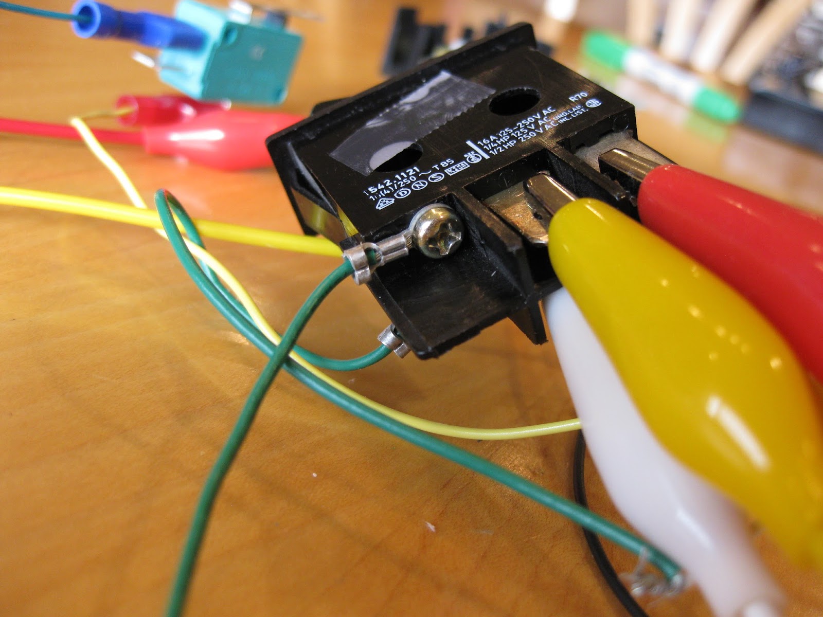
Instead, I found this one, which seems to take less force to push.  It's a rocker switch, and I'm not sure if that will cause any other problems, like slippage when the arm hits the switch.
From the side profile, you can see into the workings of the switch.  When the switch is pressed down on one side, the metal tab is raised up on that same side, and another metal tab snaps down on the opposite side.  In the profile shot shown here, the connection is open, because the metal tab is up and visible in the left hole.

Also, in this form, the switch is only a Double Pole, Single Throw switch.   There are tabs on both sides so that when the connection is closed, there's a current flowing from the center tab to the one on the left, both front and back.  So, I could tell when the switch was "on" through two closed circuit connections, but could not tell when the switch was "off", and I'd need that to retract the motor.

What I wanted was a Double Pole, Double Throw.  Fortunately, the physical mechanics of the switch allowed for it.  I just didn't have tabs under the side that would let me know the switch was "off".  In inspecting it further, I also found there were holes under that side that might give me a shot at establishing a connection.
I dug around again through various sets of screws until I found ones of the right diameter such that I could get them to self-tap into the hole.  I also made sure they were made of a conductive material.  The first ones I chose were too long, though.  If inserted too far, they would prevent the switch from operating.  After a bit more digging, I found ones that were the right length.  I also found a green grounding wire with circular clamp connectors already wired onto them, so I could cut that in half and one for each of the sides of the switch.

Wiring

I figured the logic is just a 2x2 logic diagram like the following.  You have a double-pole, double-throw switch, and you have a contact switch (CS) to shut off the whole device when the arm is down.  The logic:
CS up (open) & switch ON = extend arm
CS down (closed) & switch ON = extend arm
CS up (open) & switch OFF = retract arm
CS down (closed) & switch OFF = do nothing, system is off and now power is being used.

This assumes the system will hit the contact switch upon full retraction of the arm; the contact switch will go into an open state as the arm is being raised; and the arm will hit the "off" switch at some point as it's being raised.  Hitting that "off" switch is the whole the idea, right?

Here's the initial circuit diagram sketch.  The "OFF" and "ON" labeling of the motors is a little weird, because of how the tabs under the rocker switch are opposite from the labeling.

Laying out the same diagram in a more appealing way, you get this:
As such, when the rocker switch is on, you get this:
thus connecting V+ to Orange, V- to Blue, and the motor turns.

But when the rocker switch is off, you get this:
So when the rocker switch is OFF, if the contact switch is also making a connection (switch is closed when "up"), then you get V+ to Blue, V- to Orange, and the arm retracts.  But when the arm fully retracts and causes the contact switch to open, and the circuit draws no power.

The worm gear assembly holds the arm in place so the spring force of the contact switch arm should not cause it to auto-open again.  (If needed, I can add a capacitor somewhere in here to slowly drain and still feed the motor for a little while after the contact switch closes, too.)

I've seen some diagrams showing a regulator that's used to step down some higher voltage (e.g., 12VDC) to the required range for the motor, and that could be put into the system in place of the batteries.  But for me, I think I'll go with a cheap 4-pack of AA batteries.

As such, the wired-up motor assembly looks like this.  (In this picture, the battery is disconnected, else it would run the motor since the contact switch is "up".)


Testing it by hand is a little complicated.  You have to remember to hold the contact switch in its "down"/open position, and release that switch manually after you switch the rocker to an ON position, simulating what will happen physically as the arm goes up.

Arm connection ideas

I'm intending to latch onto the spur gear in some way.  I don't think I have the full gearing assembly that would allow me to reassemble the original gears of the paper feed in the right way.  I might, but it's not worth searching.  I think I might instead laser-cut a thing I'll call the "hub" that goes around the spur gear, and then let other things join to it.

The spur gear I'll be enveloping is 9.74mm outer diameter, and has 16 teeth.  I'm using various resources to determine how to measure a laser cutter's kerf, compensate for that kerf, and generate gears with the right dimensions.

The hub can have as much as a 16.35mm outer diameter, and only needs a hole inside of it that fits snugly around the spur gear.  But, I'm also going to drill/cut holes into it so that I can attach the UM arm to it.

Since I'm laser-cutting it, I could also make the hub less massive, using four arms instead of a full cylinder.  That's how I've seen adjustable spindle mounts shown, and that's what seems to be on the end of servo motors.

The UM arm will have the same "gear hole" as the enveloping cylinder, and will have the same drill holes.  I'll probably make it out of some less massive material, but something strong enough to push the "off" button of the UM.  I think I'll either use 5mm ply or 3mm acrylic.  The front of the arm will need to have something strong attached to it, and I'm not sure how I'll get that.

I might need something simple like a rubber band strapped across the end so that it has friction to push the rocker switch.  Other UMs are pushing a simple toggle switch, so the force is more direct, and less prone to slippage.

Printed Circuit Board

I was getting all psyched to make my own PCB using laser print / iron transfer / etching.  So, I fired up Inkscape to draw the circuit.  As a quick starting point, I began with a drawing of a simple perf board, using 2mm-square copper pads, and 1mm circular holes within the pads.  It looks like this:
Pretty basic, right?  In Inkscape it's pretty easy to do, but you have to use the data entry fields to make one square exactly 2mm, then put one white circle in it, exactly 1mm x 1mm, and center them up, and group them.  Then, duplicate and set the X and Y locations specifically, 2.54mm at a time.  Keep on duplicating and offsetting sets of these, and you get a whole perfboard (and a cool optical illusion, too).

So then I started laying out the pads and labels the same way as the pencil sketches.

But after I'd done that, I realized that keeping the pads in the same positions as shown in the sketch was not necessary.  That is just forcing the physical layout of the switches and such onto the board.  So instead, I followed the connections, trying to keep the pads proximate where there are connections.  I ended up with this:
I can rotate the pin assignments counterclockwise twice, and end up with an even simpler diagram:
In the end, it's a bit of a disappointment, though.  No fancy circuit diagram here.  It's just a bunch of bridged pins.  I can just attach two 6x1 connectors to a perf board and bridge the wires and be done.  That will be easy and way less likely to stain anything, compared to etching my own PCB, but I was a little sad because I had been looking forward to doing PCB etching chemistry.

(Yes, I could just solder the wires from switches to other switches and to a battery holder, but I want the components to be pluggable.)

When all was done, I ended up doing the wiring using screw terminals so that I could undo things easily later.


Figuring Out the Hub

I spent over two hours at the Tech Shop in Menlo Park yesterday cutting lots of things, and eventually forming the basis for the hub.

In prior laser cutting, I learned about how to cut gears, and how those gears, when meshed together, weren't meshing quite accurately.  That was because of "kerf", which is the material lost to the cutting process.  It was somewhat pronounced for the wooden gears that I cut earlier.

I made a little drawing that would cut 20 lines out from some material so I could see what was being lost.  Here's an idea of how it looks.  The little strips of wood in the middle are all bunched together, and the gap (here showing about 4 or 5 mm) can be divided by the 20 strips to get a rough estimate of kerf.
Kerf measurement on Tech Shop MP Laser #1 (45watt Epilog) using 1/8" plywood


To cut gears, I was using this site:
 makezine.com/2010/06/28/make-your-own-gears/
I used Inkscape as presented, but there are additional tricks.

Then, you have to understand the term "circular pitch".   The site listed above shows "circular pitch" as the distance between teeth on one diagram, and then shows Circular Pitch (p) = PI() / Diametral Pitch (P).  Above that formula, it shows that Diametral Pitch (P) can be computed if you know the number of teeth (N) and the Outside Diameter (Do) using the formula P = (N + 2) / Do, though it says that's approximate.

In the UM spur, we have 16 teeth, and an approximate outer diameter of 9mm.  Plugging that all in, I get:
P_in_mm = (16 + 2) / 9.72mm, or 1.85185... mm.
p_in_mm = PI() / P_in_mm
p_in_mm = 3.1415926536 / 1.85185... = 1.69646 mm.
p_in_pixels = p_in_mm / (25.4mm/in) * (90pixels/in)
p_in_pixels = 6.011078857 Inkscape pixels

Inkscape's menu appears to dumb that down to 6.0, and I'm not sure if it recognizes the remaining precision.  When it's done rendering you get this:


Compensating for kerf when cutting the UM gear hub

The next trick is that you want to get an outer cut line and an inner cut line in order to adjust for kerf.  I used the second set of instructions at
http://www.instructables.com/id/Laser-cut-Marquetry/step3/Compensating-for-Laser-Kerf-2/
to figure this out.  The instructions there aren't entirely complete, I think, so here is my full set of instructions:
1.  Select the gear
2.  Duplicate it to save it somewhere else, in case you make multiple of these (optional)
3.  Select the one you want to modify.  In the bottom left, you'll see Fill: Unset and Stroke: Unset.  This is because it's still "grouped".
4.  Select the gear and choose Object / Ungroup.  Now, in the bottom left, you'll see Fill: None and Stroke: <black bar>.
5.  Set the stroke width.  Choose Object /  Fill and Stroke... and then click on the "Stroke style" tab
6.  Enter the kerf size in the Width field, and remember to choose mm as the unit.  The interface is fussy sometimes, so you have to click another tab for the value to be applied, and it's a good idea to go back and check to make sure the value you wanted is in there.  Keep trying.  Eventually it sticks.  Depending on how much you change the value, the change in the visual rendition may be subtle.
7.  Now break it apart.  Before you do that, you might select your gear and click on the tool, and you'll see the individual vectors defining the gear like this:


Select the gear now using the regular selection tool , and choose Path / Stroke to Path... Now, if you use the tool, you'll see it's been broken up quite a bit like this:

so now there's an outer edge and an inner edge.

8.  Next you separate the inner and outer edges.  Select the gear using the regular selection tool again, and choose Path / Break Apart...  The whole thing turns black, but that's because you now have two objects, both with black fill, no stroke paint.

9.  Fix up the paint, so go back to the Fill and Stroke pane and its "Fill" tab, and choose no fill


(which makes the whole black pair of gears disappear, but don't worry...)
and then go to the "Stroke paint" panel and choose the solid box for "Flat color"

 and finally go to the "Stroke style" tab and enter a minimal stroke width, like 0.01mm


You should now see two gear edges, one inner, one outer.  Each is separately selectable.

The inner edge is the one that you use for creating a hole, and the outer one is the one you use for creating a gear.  (Same applies for other marquetry that's not related to gears, as long as you know the right kerf settings to use for different types of material.)

One thing to note at this point: Inkscape's functions for doing this are not precise, at least not precise enough for those pixel-perfect among us.  Here's a zoomed-in view of the result, and you can see some jaggedy edges that really should be smooth.


The whole thing should be governed by gear formulae, so other tools for gear generation might be better, and there probably are ways to fix Inkscape's code to generate the gear's edges in one go by taking the the Gear module source and fixing it.

The other thing to note about gear drawing is that if you save as .svg and import into CorelDraw, at least into the x5 version I was using at the Tech Shop, it would get some really ugly results.  Sometimes you'll see a quarter of the gear missing, and often you'll see vectors zooming off to distant lands.  I'm guessing gears are defined with cubic-splines, and there's a difference of opinion about how the Z (closure) code in SVG is supposed to be interpreted, but that might only explain a part of the problem.  Somewhere between Inkscape output and CorelDraw input, there's significant disagreement about the SVG standard.


Back to Laser Cutting the Gear Hub!

So at this point, I found that the wood-cut gears at this resolution were generating a lot of ash, and shifted to acrylic.  I had both 1/8" and 1/4" (6mm) acrylic to use.  So I made a pattern with a variety of kerf widths like this in Inkscape.  I had kerf measurements at this point, but opted to do some empirical testing.
I separated the inner from the outer gears, and cut both out of the 1/8" acrylic and got this:

The top edge is the set that actually cut gears out, and the bottom set is different holes that those gears could fit into.  That allowed me to test for fit to see whether any of those came close, and the 0.3mm hole fit quite snugly on the UM motor.


I then went to the 1/4" acrylic and did the same.  The intent was to create the "hub" using the thicker plastic and use some holes that could be used for attaching the arm.

From there, I went about building the hub.  That amounted to moving the 0.3mm "kerf gear hole" to the origin in Inkscape, and then building a circle around it.  I'd measured and figured a 16.3mm radius would just fit.  That allowed me to add some extra holes at specific locations within the hub as mount points.  When done, I grouped it all up and put it onto the page for cutting.  The result was a nice hub that fits nicely onto the spur gear.

At this point, I was close, but not quite done.  First, the 1/4" acrylic hub is looser than the 1/8" acrylic, even though they're using the same gear hole.  It's likely that's due to different kerf for different materials, or because I had to use two cutting passes to get through the 1/4" acrylic.  I'm not sure if I'll bother to fix that.

The second problem, though, was that the hub was running into the metal plate that covers the motor assembly.  So, I needed a little bit of room to lift the hub higher.  I resorted to the Dremel to cut out and sand down one of gear holes from my 1/8" acrylic, and formed a little spacer.  This will go under the hub.
Later, I added a few drops of epoxy to the spacer, set the hub atop it, and and held it together, so the spacer, and hub are attached.  Then, I screwed an arm onto it, so it's all held together.  The only thing left is finding a way to keep it from falling off.

The Box
I spent 2+ hours at the Tech Shop cutting up the pieces for the UM box and arm.  The handy things to know are the Corel Draw features for
- setting up specific sizes (use the data entry fields in the top left, and be sure to turn off the "maintain aspect ratio" constraint), and adjusting sizes for kerf
- adjusting for how Corel Draw likes to use the center point of objects as the object's origin -- a pain
- the "C" and "E" keys for centering objects, plus the Undo ctrl+Z if you choose the wrong one
- undoing the usual Snap To... function
- welding to build out the joining tabs (select multiple objects, choose the weld icon)
- the opposite of welding for cutting slots
- rotating 90 degrees to get exact dimensions for adjoining pieces
- mirroring objects so that you get the right material face on opposite ends of the box

Pictures:

Full box with original motor for scale.  Note that there are two test boards for containing the switch at different points, so I could test various configurations.
These are the individual pieces
Box assembled with the three-slot test board
 The way I built the box has tabs connecting the sides and bottom, but the top is loose.  I wanted to do that for a clean look, but now I'm not sure how the hinge assembly will work, unless I make the hinge visible on the exterior.

For the arm, I drew up an arm and roughly cut it with a Dremel tool before going to the laser cutter. You can see the rough pencil markings.  Definitely, this is not engineering with CAD tools.


Then, I scanned the arm in to a normal .jpg file along with a ruler so I could be sure dimensions were accurate.  I used Corel Draw's Import function to pull in the image, and then traced a polyline atop it.

I think there was one tricky part where I had to select all the segments and run the Smooth function on them, thus turning them into curves, where before I had a polyline.

Then, I overlaid a circle and welded it to the curves to get a really nice hub point.

I made a couple of copies with varying "finger" widths.

I didn't have time to laser-drill the pilot holes to match exactly with the ones I had on the hub, so I just drilled those by hand later, and found some wood screws that fit.  From there, I just had to bodge things roughly into place such that the arm could hit the Off switch somewhere in its movement path.  I also checked to make sure that in its retracted position, it would fit inside the box, including room for it to hit the contact switch.


Laser-cut arm placement with Off switch down.
The motor assembly was loose so I did end up cutting away some of the original plastic tabs, and used those holes to screw it onto an extra piece of wood that I had.  That piece of wood was actually a failed cut for the box, one where I'd not accounted for the tabs, but as it turned out, that made it the perfect size for fitting on the inside of the box.  I then glued that whole assembly to the back wall so that the motor would not fall over any more.  If I don't like it later on, I can unscrew the motor assembly and recut the boards.

For the bottom of the box, I found that I'd need to raise the contact switch up a bit, and position it about half way deep into the box.  I found a scrap piece of 1"x1" wood, cut it to length, then screwed the contact switch to it, and glued the wood to the base.

Separately, I checked and found that there's enough room for the battery pack, so I'm good there.

Final assembly(?)

Here's are the "finished" pictures.  It's not really, truly done, and I think finishing it for good will take more work than I'm willing to put into it.  The problem that remains is that the arm, though glued onto the motor gear, ends up moving the motor's main gear a bit when it gets into a strange angle, and that causes sufficient tension that stops the whole device from working.

The outer box is held together by rubber bands so I can undo things if I want.  This picture was taken before I moved the batteries inside the box.
Most of the time, the switch operates as expected, but when it fails, I end up having to wiggle the box a bit to loosen it up, and then it starts working again.  I tried various ways to add tension to keep the gears from coming loose.  I added foam to push against the system, and tried something akin to a bearing.  I tried drilling a hole in the front panel (seen in the picture above) and added an adjustable wood screw to provide an adjustable amount of tension.  But still it doesn't fully work.  It may be that using a worm gear drive just isn't the way to go for my UM.

The innards look like this.  This is the view from above.  It's a little hard to see, but I've hot-glued a chunk of foam onto the contact switch.  That makes for an earlier and more sure response from the switch.  Before I had that in place, the lowering of the arm would miss the switch sometimes, and sometimes I think it would over-compress the switch.
The next picture of a view from the back with the back panel down.

It's not shown here but I finally put the battery pack inside the box.  It's running on about 15VDC using a 9V battery in series with four AA 1.5V batteries in a pack.  I found that at lower voltages -- 9V or below -- the arm moved more slowly and didn't have enough force to click the Off switch.  I've also seen some failures at 15VDC when it would try to click the switch too close to the edge.  It works better when it clicks nearer the middle, which is a bit of a surprise for me, since I'd have thought it would have greater leverage towards the edge.  I didn't try at 12V.

I've decided I will not glue the whole assembly together because of how the system actually benefits from the looseness.  In a more precise assembly, I think I would be able to hold things together firmly.

Finally, here's a video of the machine in action.  I edited out the part where clicking the switch failed.  But I'm glad I could capture some instances where multiple clicks worked. 

<< Bummer... Blogger isn't uploading my .avi or .mp4 file! >>

Useless Machine v1 was a pretty good prototype experiment.  Some thoughts on where I might go next with it:
- Learn how to create a mold from the main gear, and how to run the injection mold machine to make copies.  With those, experiment with other ways to add tension and get consistency.
- Re-cut the front panel so I don't have the hole I started with.  Maybe engrave it with a nice logo.
- Create a v2 UM with a more solid DC motor driving a worm gear, and having the worm gear connect to a pivot arm in a more predictable build and with channels that prevent the arm from straying off course.
- Figure out a hinge mechanism
- Re-cut the top panel so that the arm moves with the grain of the material.  Right now, it moves across the grain.
- Re-cut the box using acrylic
- Make a super-sized UM

But maybe instead I'll do something else.  I'm having some thoughts about making an Arduino-based thing that gets plugged into the wall and tracks current usage, and sends a text message alert if something has been plugged in too long and is still on.