Monday, December 27, 2021

The Claw!

Just in time for Christmas Eve, 2021, we completed The Claw!


This is a project that was a befuddling concept from July, 2021 until November, 2021. 

In initial conception, I mainly looked to the Arduino Claw Machine v4 videos on youtube.  The concerns rolling in my head, in no particular order, were:

  • How does the claw mechanism work?  How much power does it need?  How much does it weigh?
  • How do people do the linear motion for these?  Lead screws?  Belt-drive mechanisms?  Rack-and-pinion?
  • How will I build a frame for it?

Sadly, due to the pandemic, I'd lost access to my preferred makerspace.

It was my good fortune in July to have gone to a garage sale where they had been remodeling, and were giving away some clean bathroom cabinets.  Those would form the basis of the physical structure.

I ordered a solenoid claw on eBay in July, 2021, just to get an idea of how it worked.  I was surprised by how heavy it was, and that made me think that I'd need a strong framework for the X-Y linear motion mechanism.

The Cubex Duo

In November, the project got a big boost when a friend gave me the frame of his old Cubex Duo 3D printer, after he'd heard I was building the claw machine.  


The machine had a belt-driven motion assembly and reed limit switches for both axes.  All of that was working.  The print bed and extruder and hot end were removed, and weren't necessary for my build.  The main frame was comprised of 12mm rods in a cube layout, where the rods were about 18 inches (500mm) apart.

The Cubex also came with a BigTreeTech SKR 1.3 motor driver board, and several BTT TMC 2209 v1.2 motor drivers.  There was a 12v power supply, too, but I ended up using a separate DC transformer.  (This was only because I was doing prototyping in my kitchen, and the 12v PSU would pop the GFCI circuit.)


For my purposes, I intended to use the joystick signals to indicate motor movement, and just step the motors in different directions.  The SKR 1.3 motor driver board was more geared toward having a Marlin implementation set up on it, and having motion managed by gcode.  I ended up just using the TMC 2209 boards directly, leaving the SKR 1.3 out of it.


Unfortunately, most web sites that talk about the TMC 2209 don't address direct usage in an Arduino style.  I had hoped to take advantage of some of the sensorless homing capabilities of the drivers.  After a few experimental attempts at that, I just went with a basic bit-banging implementation.  That worked out really well, and I still got very quiet motor movement.

The Cubex Y axis actually has two NEMA 17 motors driving belts that move the X axis motor and rails.  With some clever wiring, they made it such that both motors could be driven from a single stepper controller.  In fact, the machine could run with just one or the other motor, as long as it's properly lubricated.

The Cubex X axis moves the print head platform left and right.  That platform rides along two 12mm rails and has its own magnet for triggering the X axis minimum limit reed switch.

When I got the Cubex, it still had its NEMA 23 motor and centered lead screw that would have raised or lowered the print bed.  I didn't need that motor or lead screw, so those were removed.

The Z axis (spool/winch)

For this build's Z motion, I needed a reel or winch-type assembly to reel in or release the cord holding the claw.  I didn't want to disassemble the platform, because it was already clamped to the X axis belts, and properly tensioned.  Instead, I measured it and chose to use its center hole for the rope.  


I printed a NEMA 17 motor mount so that the motor could directly drive a spool.  That was designed to allow it be held in place with screws and fender washers, but I ended up placing it with double-stick tape, and it remains that way now.  I might revisit that when it comes time to transport the machine, especially if I have to lay it down sideways.


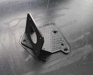
I lathed the spool out of some excess hardwood.  One end of the spool had a 5mm hole and set screws to attach it to the NEMA 17.  The opposite end had an 8mm nub sticking out, and that went into a pillow block.  The pillow block rested atop another printed plastic block so that the spool could run level.


The claw rope isn't held to the spool in any clever way.  It's just taped to the interior of the spool, and sufficient excess rope is wound around it to keep it in place.

There is a printed gland that the rope goes through, and it serves two purposes.  First, it prevents the rope from chafing against the sharp aluminum edges of the platform hole.  Second, it has mount points for a microswitch.  I used an existing microswitch and bent its metal lever so that it'd be hit by the claw.  That serves as my "Z up" limit switch.  (The picture shown here has v1 of the gland, where I hadn't added the limit switch mount points yet.)


This is "version 2" of the gland, shown from below, including the Z limit switch.  The gland was extended to be a longer tube, and the microswitch is held in place with just some twist ties.


Breadboarding motor controllers

The TMC 2209 motor controllers are mounted in two 1x8, 2.54mm pitch, female headers.  Those, in turn, are soldered to solderable breadboards (ElectroCookie 9 pack, $21).  One easy mistake to make with TMC 2209 boards is to have their DIAG or INDEX pins touch the breadboard.  I bent those out of the way but kept them in case I reuse them in some other way in the future.


I wired up the TMC 2209's in a pretty basic way.

  • EN is always low, hardwired to GND.  As such, I don't control motor enablement in software.
  • MS1 and MS2 are set for half-stepping.  It's interesting to note that these same pins are used for UART addressing.  Many web sites don't mention that.
  • I'm keeping the motor voltage and ground isolated from the Arduino 5v and GND lines.  Some sites suggest tying the Motor and Arduino GND lines together, but I like the isolation.
  • The motor outputs are connected to JST-SM headers (pack of 20, pre-wired, $10).  While not as neat as having JST-XH headers, these JST-SM sets allowed me extra wire length, and it was nice having four wires for each.
  • I did put in a 100uF 50V capacitor across motor GND and motor V.  The specs typically call for a 47 uF or larger cap there.  If you're using a motor carrier board, it's probably built on to the board already.  (NB: specs also call for small caps near digital GND and 5V, but those actually already are on the TMC 2209 boards.)

As I soldered breadboards, I found that it was useful (from a physical layout perspective) to have the limit switch signal lines of each axis co-located with the axis motor lines.  

Solenoid and relay

For the claw solenoid, I found a 30V power supply at the thrift store.  Based on what was written on it, I think it was originally for some kind of powered speakers.  I wired that through a relay module and it worked fine.  I'm pretty sure the relay module has built-in flyback diodes to avoid reverse power spikes that solenoids can generate.


Sound

The sound system is built using the Mini DF Player module.  I had some of those from my earlier R/C Roomba project.  That took a bit of getting re-familiarized with the module and its quirks.  


The main things about the DF Mini Player:
  • Communication is done on a Serial line.  The Arduino TX line runs at 5V and the module's RX runs at 3.3V, so you have to step it down or reduce it in some way.  Many sites just have a 1k resistor in line between the two.  I don't totally get how that works, but it does.  There was one site showing how they'd voltage-divide it down to 3.3, and I think that's a better reasoned approach.
  • For my purposes, sound files go onto a FAT32-formatted SD card and within the /mp3 folder.  They must follow a nnnn_<whatever>.mp3 file naming convention.  And despite the numeric nnnn prefixing, the actual play order and file indexing is based on the order in which the files are added to the SD card.
  • The Busy line coming from the module is directly useful.  There are some sites out there where people are asking, "How can I tell if the song is done playing?" and then people tell them to use the API to figure that out.  Instead, I wired directly to BUSY line and check its value with digitalRead.
  • I couldn't find a way to pause a song and resume it.  Ideally, I'd want to signal recognition of a coin drop by playing a special sound, but if that happens in the middle of a long file, I end up fully stopping the current song, playing the "coin drop" song, and then not restarting what I'd interrupted.  Of course, one way around this would be to have a second Mini DF Player.

Front panel controls

I'm using an original Mortal Kombat arcade joystick.  I probably could have used something with less authentic retro cred, but it was kind of cool to use the real thing.

The arcade button is a typical one you can buy these days that has an internal spring and causes closure of a mounted microswitch.

The coin mechanism made of three pieces: a "slot" piece, a microswitch mount, and the microswitch itself.  The slot piece has a hole 3mm wide and about 24.5mm long to allow a US quarter to slide through.  It's a simple, straight drop slot.  Shown here is the original design with countersunk screw holes that, as it turns out, I didn't really need.  (Ideally, it should drop mount holes from above, and allow screw attachment below.)
 
The lower piece allows the microswitch to be mounted.  I ended up just using a length of wire (blue in the picture below) to twist-tie the microswitch to the mount piece.  The switch's metal lever was bent so that the coin would hit it firmly while passing through.  In early prototypes, the coin would get stuck, held up by the switch lever, but it works fine.


The Arduino loop polls the coin on each pass, and it's fast enough to recognize the coin drop without needing an interrupt.  It also ignores duplicate coin slot signals within a 1 second period.

Keeping the signal wires tight

The front panel electronics -- joystick microswitches, button microswitch, coin microswitch -- all connect their lines through an MDFLY ethernet breakout board.

 
There's one of those boards on the Front Panel side, and one near the Arduino.  That allowed me to use terminal block-style wire clamping to arrange all the wires, and neatly carry all the signals from the cabinet front to the cabinet back using a single ethernet cable.  
 
The ethernet cable allows me to have one GND signal, four signals for joystick, one for button, one for coin.  There's one spare that I could have used for something like an electric eye to detect a win, but I ran out of time to build that.

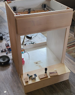
Motion control prototype

During this phase of prototyping, the Cubex Duo was just that -- a cube.  It's shown operational here.


By the time the project was completed, the Cubex Duo was reduced to just the top "square" of what was the printer.  That is, I am using the four top 12mm rods of the frame, the four top machined "cylinders" that hold those rods together, the original X axis with its drag chain assembly, and the Z platform.  All the vertical supporting rods, and the bottom "square", and the bototm Z axis motor were removed and saved. 

Physical structure

Physically, the main framework of the build is two bathroom cabinets, one stacked atop the other.  The front panel is attached to the upper cabinet.  
 

Upper cabinet

The claw motor assembly barely fits inside the top portion of the upper cabinets.  I added a few boards to support the cylinders better, and routed out a few sections to allow space for the drag chain assembly.

Though the Cubex top section is slightly too large for the cabinet interior, I found that the cabinet's removable front panel gave me the extra space I needed.  But, it also was too much space, allowing the top section to fall, if the whole thing were to slide forward too far.  To prevent that, I printed a few blocks to keep the cylinders from moving too far.  Shown here is the front, left cylinder with supporting wood and black plastic block.  I've also put the frame on felt pads to reduce vibration, so that's the little black disc under the metal cylinder.

Front Panel (physical)

The front panel was built from 1/2" plywood.  I measured multiple ways, and prototyped it with hardboard.  The plywood pieces are joined using printed L brackets.  When done, the whole front panel was screwed to the cabinet's front edge at five points, and held to the cabinet sides with metal, 4" mending plates.
 
This is the front panel / upper cabinet assembly as it evolved, before the FP was attached to the cabinet:
The main difficulty with the joystick (and other similar joysticks) is that you have to undo a C clip to install it.  It's screwed into the front panel from below.
 
For both the joystick and arcade button, I used a 1" spade bit.  I cut in (drilled in) from both the top and bottom to avoid tearout.  I still needed to sand a bit to get the button to slip in, and I used a Dremel to chamfer the edges for the joystick.

This is the FP underside:


To get the slot cut out of the front panel, I printed a separate template to help me drill 1/8" holes, whose edges wouldn't go past the ends of the "slot" piece.  That's the grey rectangle in the picture above.  I then used a scrollsaw to cut the section between the holes, and then cut into the "corners" of the rectangle.  It would have been easier for me to re-print the "slot" piece in such a way that it could hide my mistakes, and allow screw-in attachment from behind, but I ran out of black PLA at the end!

The ethernet cord goes through the base part of the upper cabinet.  I drilled 1/2" holes, but should have gone larger.  I ended up having to cut extra out.
 

Electronics (PC) assembly

In all, the computation part of the machine was comprised of
  • One Arduino Mega 2560
  • One breadboard for the X, YLeft and YRight motor drivers
  • One breadboard for the Z motor driver and MiniDF Player module
  • One mini breadboard for hardwired pull-up resistors
  • One MDFLY ethernet board (to talk to the front panel via an ethernet cord)
  • One relay module (for the claw solenoid) and the appropriate jack for the 30V power supply
  • One wire connector for the 12v motor supply
I call all of that together the "PC" for the claw machine.
 
The PC components are all mounted on a piece of spare acrylic using nylon M3 standoffs ($12). Shown here is initial layout, and then standoff placement.  I didn't do this in a super precise way (using CNC to drill holes).  Instead, I placed the components, marked holes using a fine tip Sharpie, and drilled by hand.  I feel good about the non-conductivity of the nylon standoffs, but some of the nuts/screws didn't thread all that well, compared to brass standoffs.


Here's what it looks like with components attached to the PC base.

The top of the PC is another piece of acrylic, cut to the same dimensions as the PC base board, but with a section cut out to allow room for the ethernet cable.  

I used 2.5" lengths of 3/4" square hardwood (3' length, 3/4" hardwood square, Home Depot, $4) as standoffs separating the PC base and top.  I put those in as an afterthought, figuring out their safe placement only after the PC components were screwed down.  I used a pen lathing vise and a drill press to get consistent, centered holes on both sides of each "standoff" wood piece.  The standoffs were drilled to accept #6 x 1/2" screws, and the acrylic had corresponding larger holes that would allow pass-through of those screws.  I used countersink screws only because they were available.  Using hex-head ones would have been better.


Front window

The front of the game cabinet is a big sheet of acrylic with a hole cut out for prize access.  Its top slots into the same wood piece that I used for supporting the Cubex Duo frame.  That was routed out in several passes to accommodate the acrylic thickness and also allow for some slop in case I cut the acrylic poorly.
 
This is the front frame before painting and protective plastic removal. The T-shaped "window frame" originally was the cabinet spacer on the right side of the cabinet.  Note the screws now holding the FP to the cabinet.


Hopper bin

The "hopper bin" is a bent piece of acrylic held to the game area base by L brackets (wood screws into base, metal #8-32 screws through the hopper bin plastic).  I modeled that initially with cardboard to get a sense of size and to make sure its dimensions would be appropriate for the drop zone of the claw. 
 

I was pleasantly surprised with the acrylic bending technique.  I used a hot gun on low setting, warming the acrylic for a little over 2 minutes.  Then, I bent it over an edge of a makeshift vise.

This mostly worked, but to make sure the edges were square in both dimensions, I reheated it and bent it within a garage cabinet.  That let me keep an eye on the alignment of all the edges as it cooled.

Back panel

The cabinet back panel is just a sheet of 1/4" plywood.  We added contact paper on the inside to hide its wood look.  Holes were cut out of the top to allow the motor control, solenoid, and limit lines through.  There are three 3D-printed pieces that keep it in place, two on the bottom, and one on top.

PC-to-Back panel mounting

I printed my own panel holders to support the PC on the back panel.  They provide about 5mm separation between the PC base and the back panel, allowing room for the standoff nuts and such.  There are six of them holding the PC in place.  

 I only had #6 x 1/2" machine screws and nuts for this part, and they extend as far as I wanted to get through the back 1/4" plywood panel and Con-Tact paper, so I used the heated insert trick: I put a hot soldering iron to the screw, and melted it into all but one of the 3D-printed panel holders.  That got the screw in farther, and also made the screw fixed to the plastic.

Roof

There is a simple hardboard panel that serves as the roof for the machine.  I drilled holes so that it could be positioned using the cabinet's existing corner braces, which I assume had holes for holding a countertop or similar.  The holes allow bolts to keep the roof in place.  But, I chose not to actually have nuts attaching the roof firmly.  That way, one can open up the roof to do repairs or even toss in toys.

The roof also serves as the mount point for interior lights.  But since it's hardboard, and the rough side is on the inside, it's not something that would work for adhesives, such as are found on LED light strips.

Speaker

The speaker is visible in the picture above at the lower edge of the PC board.  By size and shape, I'm assuming it's a typical coaxial car stereo type of speaker, and thus probably 4-ohm impedance.  (The DF Mini Player specs I've seen online recommend 3-ohm or higher impedance.) 

Out of sheer laziness, I attached the speaker with just one screw to one of the bottom PC wooden standoffs.  That saved me the effort of cutting a speaker hole, etc.

Lighting

The initial build didn't have any lighting.  It looked good in earlier pictures, but that's just because it was positioned under a garage light fixture (exposed LED T4 bulbs) with the roof off.

I had three under-cabinet, LED puck lights that ran on 12v (1.1W) so I positioned them inside -- two in front, one in back -- and hooked them up.  The wires ran out the back, and all I had to do was power them.

Using the same power connection point as the motors, the lighting was pretty good.  It wasn't as bright as the garage lighting.  The problem was that the lights flickered a lot as the motors would run.  I was using a 12V (measured 11.5V), 2.1A wall wart.

I tried running the lights off a separate 12V supply and that went better, but the lights constantly flickered.  I attribute that to having a bad power supply.

Finally, I got a 12V, 4A wall wart, and used that on its own for both motors and lighting.  That went well, so now I have lights.

Cabinet stacking

The upper cabinet is stacked atop the lower cabinet.  I used some spare 1/2" plywood to make something akin to mending plates in order to join them.

These mending plates were roughly 6" tall and 10" wide.  I kind of blew it with their positioning.  Originally, the plan was to mount them near the rear of the cabinet.  That's because cabinets come with a toe kick area, which makes the range of placement shorter for the upper cabinet.  I just habitually put one side's mending plate centered, and then did it the intended way for the other side.  Measure twice, right?

The mending plates were sanded on all edges.  Part of the reason for that was so that the upper cabinet could slip over the plates more easily.

I pre-drilled 3/16" holes at four points on each plate, and drew a midline horizontally on each.  With the midline facing outward, I positioned one on a side, and drilled 1/4" holes through the plate and the lower cabinet side wall.  I used 1/4" carriage bolts, so I had to make a little extra room for the "square" inner portion of the bolt head.  I had hoped that simple compression into the cabinet wall's MDF would work, but the MDF was too strong for that.  So, I ended up using something like a 19/64" drill, and just drilled a small amount inward to help seat the bolt head.

After both plates were installed on the bottom cabinet, we lifted and positioned the upper cabinet on top, sliding it over the mending plates.  Then, I repeated the hole drilling -- again from inside to outside -- on the upper holes of each plate.

This is roughly what it looks like on the inside, though by the time I'm done it'll have fender washers.  Without fender washers, due to how soft the plywood is, the nut and lock washer bite too deeply (for my tastes) into the wood.

This is the outside appearance.  Using these kinds of carriage bolts is nice, because they have a smooth surface, meaning now unscrewing/unbolting it from the outside.  Also here you can see the mending plate that keeps the front panel attached to the upper cabinet at those side points.  I couldn't hide those as easily, because I didn't want to break the structure of the toe kick plate of the upper cabinet.


Painting and cosmetics

My wife did all the painting of the exterior and interior of this, and it really made a difference.  We used black semi-gloss (Behr Urethane Alkyd Enamel, Home Depot, 29 fl oz for $18!!).  That stuff has gotten so expensive!

It was really cold and humid during the build, so the paint wasn't completely dry by Christmas Eve.  We accelerated some of the drying by moving smaller parts indoors, and using a heat lamp on the upper cabinet.

Inside the cabinets, we used Con-Tact white shelf lining.  Doing that as a two person job was a requirement, at least the way we were doing it.

Doing both the painting and lining made the machine look much, much better.

Power

Finally, the whole thing is powered by single power strip that has the 30v solenoid power supply, 12v motor and lighting power supply, and USB wall wart (to power the Arduino).

Software

The software structure is a fairly simple state machine:
  • Init state does X, Y, and Z homing and moves to Advert mode
  • Advert state plays a random song every 15 seconds.  If credits are added, it moves to Play Intro state.  Advert state also moves the claw to a Y position of 100 steps.
  • Play Intro state plays a start song, waits for it to end, and then moves to Play state.
  • Play state looks for joystick and button operations.  Joystick positions set up dx and dy values of 1 or -1 as appropriate.  If the button is pushed it moves to Grab Descend state.
  • Grab Descend state drops the claw a pre-determined number of steps, and then goes to Grab Engage state.
  • Grab Engage state activates the claw solenonid and goes to Grab Ascend state.
  • Grab Ascend state raises the claw until the Z limit switch is seen (and re-zeros the Z axis when the limit is hit).  It then moves to Grab Deliver state.
  • Grab Deliver state moves the claw to the hopper bin location and moves to Grab Release state
  • Grab Release state releases the claw solenoid and goes back to Advert state, which moves the claw back to Y position 100 (which is roughly 1/6th inch from the back edge).  Part of the reason for the move to Y 100 is to get the claw over the toy bin, so if someone turns off the machine, the claw falls in an area that's away from the hopper acrylic.
At each state change, there's an option to stop the current music, set up a new song to play, and choose to put that music into repeat mode.  Each state change also has some kind of event that causes transition to the next.  The code evolved this way, and could have been written such that the states were more  like their own StateHandler objects with defined transitions and events, but it's all linear C code right now.
 
The software doesn't use Arduino interrupts.  The main thing I think of for those would have been to recognize coin drops, but even the different state transitions could have been done with interrupts.

The overall software loop does these things
  • Check to see what the current song number is.  If the DF Mini Player is busy, wait.  Otherwise, play the current song, if the repeat counter is 1 or more, and decrement the repeat counter.
  • Based on the current mode, check input mechanisms (coin slot, joystick, button, timer).
  • Depending on inputs, set up dx/dy/dz values (1, 0 or -1) and/or stop the current song and/or move to the next state.
  • Process motor controls.  At this point, dx, dy, dz are set up with some values.  If those are non-zero, and if we're not already at limit points, perform stepper motor steps, and possibly add a short delayMicroseconds delay for smoother motion (and to avoid stalling).

Additional steps

There remains one last ugly bug in the software.  If the machine is turned on when the Y axis is already homed, it seems like it thinks Z is homed.  I'm not sure why.

As it turns out, I circumvented this problem by adding the Advert state function, which moves the head to Y position 100.  I had done that to get the claw away from the hopper bin acrylic, because upon power-off, the claw drops rapidly, and I didn't want the hopper bin to be damaged.  But as it turns out, that same function moves the head away from Y position zero in this errant case, so a second boot will start normally.

I have a sneaking suspicion that the root cause of that bug is in the limit switch wiring.  I'm kind of thinking that all the limit switches should run with physical pull-ups that are the same, rather than using Arduino internal pull-up resistors.  But that's totally a guess right now.

Final thoughts

What?  "Final" thoughts?  No way, I want to make another one!

The Claw was really, really well received by the kid.  Merry Christmas!

Getting the Cubex Duo frame was the real kickstarter for this build.  When I look back at the project timeline, it went in fits and spurts from July through mid-November, but then it kicked into high gear.

Having the bathroom cabinets for the frame also helped a ton.  Overall, I was fortunate to have lots of stuff so I could do this on the cheap.  I also was fortunate to have various power tools for this.  I used almost every power tool at my disposal.  

It was super useful to have a 3D printer for this.  Modeling was done in Fusion 360.  I'm using a somewhat aging Artillery X1 and mostly printed with Hatchbox black PLA.  I printed pieces for

  • NEMA 17 mount for the Z axis
  • Z axis pillow block support
  • Z axis gland and limit switch
  • Blocks that prevent the whole assembly from falling into the cabinet
  • Back panel clamps
  • Jig for centering screw holes to attach FP to cabinet
  • Front Panel L brackets (dual and single)
  • PC supports/braces
  • The coin slot top and bottom pieces

I didn't really get to learn how to build my own belt-driven, linear drive mechanism.  Now that I've seen how they did it with the Cubex Duo, I feel like I could do it.

I don't quite understand how real claw machines leave their claws in an "up" position.  When my system powers off, the claw falls.  I'm guessing that they use geared DC motors, and it's the gearing that provides really strong physical resistance.

Next time, I'll have a better way to lay out the circuit boards.  I'll put limit switch circuits, including pull-ups, closer to each motor, and I'll plan for having limit switches on both ends of the X and Y axes.

I'd like to learn more about those TMC 2209 motor drivers and get them documented better for Arduino people.

If I were to build this again, I think I'd have a different layout of the window and window frame. 

Huh.  I should probably post a video of the thing in action.


Monday, November 8, 2021

Toy claw machine teardown

 A toy claw machine!

Of all things, while intending to make my own claw machine, I ran across this at the thrift store:

I had no idea of its condition until I started pulling it apart.  First step: the batteries.  Fully expecting ancient batteries and corroded terminals, I was very surprised to find 3 healthy (1.5V or higher) D-cell batteries within, and no signs of corrosion.

So, obviously, next step: turn it on, and put a coin in.

The machine came to life making quite a racket.  The left-right motion worked well.  The front-back motors were slow.  

 The drop bucket was completely inoperable, because the stick for it had become detached.  


It went through its play sequence and gave me a wah-wah-wah sad sound for failing to grab anything.

Other observations: the top lid was missing a red panel.  Presumably, that was there so you could put objects in, and then seal it up.  


The rear and right clear panels were busted, most likely due to harsh conditions at the thrift store.

A view from below

This is the bottom area with its two panels removed.  The smaller one allows you to retrieve coins.  The larger one is for the batteries.

Ten screws (2.67mm OD, 8mm long) later, and I had the bottom panel off.

What a horrible rat's nest of wires!  These pictures also don't show the trails of hot glue that were left wandering about, either.  Very messy.

The bottom panel holds connectors to power, the power switch, and the speaker.

I then removed the four short screws (2.81mm OD, 5.65mm long) that held the circuit board in place.  It turns out it's a simple, single-sided board.  The "up" non-conductive side holds three DPDT momentary switches.

The joysticks were a very simple, clever mechanism.  Each is a gray stick that has a T-shaped peg on the end.  The holes mate to the pegs of the circuit board switches.  In between, there is an oval red piece that provides a way for the stick to pivot.  You can remove the grey joysticks and red oval sliders by pivoting the stick and tipping it through, and then simply lifting out the slider.


Fixing the claw joystick

This is the top side of the control board.  As you can see, the peg is missing from the up-down switch.  After a little shaking, I found the missing peg, fortunately.


I de-soldered the switch so I could work on it.  Here are the bottom and top views.  If I were to replace this, I'd need something where the switch holes were 0.2" apart, and ideally it'd have the same stabilization mounting hole separations (0.4" x 0.8", roughly).


You can see where the peg snapped off of the switch.  Someone probably was too rough with it, but the peg really didn't have reasonable strengthening supports.  From a 3d-printing perspective, it'd be like having a circular peg on top of a cube of plastic -- very easy to break.

I wasn't quite sure how to fix this.  I could order a new switch, and hope for the best.  But that seemed like it'd take too long.  I also considered drilling a hole and putting a metal peg in place, but figured that wouldn't hold.  Plus, the plastic in the switch wasn't all that thick, so there wouldn't be much for the metal to bite into.  Gluing the peg back in place seemed like a path to rapid re-breaking.

Taking a chance, I assumed the plastic to be ABS and decided to try to melt the two pieces back together again.  I set my soldering iron to 235 C.  On my first attempt, I just hit the edges and it didn't provide a strong bond.  It snapped back off again quite quickly.  But I succeeded on my second attempt.  I melted the peg bottom and the switch plastic briefly, then held the two parts together and touched around the edges.  Then, I let it cool.  It came out ugly, but strong and functional.

After re-soldering the switch to the control panel and putting things back together again, it worked!

Other functions

I found out during testing that the toy also has an "electric eye" beam -- an LED and an optical sensor -- near the bottom of the drop chute.  So it assumes you've won if something crosses the beam.  (If you leave a toy in there and start the game over again, it waits until it sees a new signal, so it's a leading edge kind of detection.)  

The coin detection mechanism is also quite poor.   Most often, when I insert a quarter, it would start the game, but the coin would not fall through.  I also could just start the game by putting the coin halfway in, and then would take the coin back out again.

In any case, I found a nice test sequence, where I'd start the game by pushing the coin detect with a small screwdriver, and then wave my finger across the light beam to stop it.

Linear motion mechanism

Onward.  The toy worked, but I was still curious about how it did its linear motion, and why the Y axis movement was so slow.

I removed the ten screws (2.75mm OD, 5.7mm long) that held the lid in place, and then removed the lid.  Getting those screws off was a little tough.  They were screwed down tightly, and I had a limited range of motion because of the clear panels.

Removing the motor cover gave me a little more insight.


So... a few things to point out here.

First, it's a rack-and-pinion mechanism in both X and Y axes.  The X axis motion has two racks.  There is a metal rod connecting both X axis pinions at once, and that's connected to the motor mechanism via gears.

The Y axis movement (front-back) also uses a rack-and-pinion system with dual racks.  I think for that axis they just used two motors, one for each rack.  I think that means it's possible that they used the available voltage without amplification and thus lost speed on that axis.  It's hard to tell and I didn't want to tear apart the motor carriage further.

There are limit switches for both X and Y axis movement.  I think they're wired in series.  Certainly that's what's happening on the Y axis.  It's possible all four switches run off the same wire in series, thus reducing the wire count going back to the PCB.

The overall motor carriage was askew when I opened it up.  It took some clever loosening and re-tightening in order to adjust that.

The claw

The claw motor is running two sprocketed gears that hook into the chains that hold the claw.  But, interestingly, the chains don't both release and lift at exactly the same time.  One precedes the other by a bit, allowing the claw to open upon initial descent, and then close before coming up.  I think that means there's a rotating peg on one gear that hooks into an arc slot on the other gear.  Clever.

Next steps

I'm going to need to take the top lid off again in order to remove and fix the rear and right clear panels.  Those appear to be held on by the screwed-on corner brace columns.  But they also look like they're bent at the edges, so I might have to figure out how to bend acrylic before I'm done.

I might also investigate the Y axis motors a bit more.

Otherwise, I think this toy is a decent fallback if my "real" claw machine build takes too long or goes sideways.


Friday, November 5, 2021

Double E 561 Excavator teardown

I found this wonderful broken excavator toy while thrifting, and took it apart today to see if I could reuse the entire movement assembly, or parts of the motion works, or just the motors in another build.


First, the treads came off along with some little supporting wheels.


After that there were several (six? eight?) screws that held the base plate up.  Here's what it looks like with the plate removed.

Just by the wiring, you can see there are just two wires going to each of the front wheels.  The rear wheels spin freely as idle gears.  The front motors appear to be geared DC motors, given there are only two wires going to each.  That makes sense for a basic toy.

By the way, these things retail for around $60.  But this one is missing the entire front bucket assembly and the remote control.

The tread motors came off with the removal of four more screws each.  One thing I like about this toy is that, unlike things like H-P printers, they use normal screws, and I think there were only two or three types of screws in the whole assembly.

At this point, I hit a problem.  I wanted to remove the wheel base from the cab assembly, but couldn't get to its screws.  The screw heads were blocked because the cab couldn't pivot, being on a gear assembly for swiveling, and I couldn't activate the motors, lacking the remote control.

I did a quick power test, hoping that maybe the boot cycle would rotate the cab.  The power area was missing the battery, but was labeled 4.8v and had clear black and red wires.  So I hooked it up to a USB wall wart and breakout wire.  The cab lights lit up and flashed, but there was no movement.  That wasn't entirely surprising.

So to get the cab parts off of the cab baseplate, I had to sneak a #1 Philips (or smaller) screwdriver bit into the hole, and use an adjustable wrench to turn it until the screw came free.  Then, I was able to turn the bit with my fingers.

Fortunately, that's all it took.  The cab top came off of the cab baseplate cleanly.  There weren't any tricky, easy-to-break plastic tabs to fight.

Here it is with the cab top removed, revealing the circuit board and motors.

After looking around a bit, I found that it had the following:

- Six thin wires going up into the arm.  I could only see two, where it was broken, but there were six originally.

- Two wires to each front wheel/tread motor

- Two wires to a speaker

- Three wires to the cab so the LEDs could flash independently

- Two wires to the cab swivel motor

- Two wires to the arm motor

After removing a few more screws here and there, I had the arm off 


and the swivel motor out (the black box at the bottom, now away from the swivel gear).

From there, it was just a matter of taking lots of pictures of the circuit board, removing it, and de-soldering.

The top left chips are marked MX1508 / 1842HS.  A quick google shows those are DC motors controllers, but it's hard to find a clean datasheet without looking at breakout boards.  The breakout boards might have flyback diodes and PWM control.

 They appear to be dual H-bridge chips, thus allowing bidirectional movement in each motor.  Each chip can control two motors.

The motor connections had labels and were easy to trace.

MXB = yellow/green, thin, going up into lift arm

MDB = yellow/white, thick, for lift arm 

MWX = blue/red, thin, going up into lift arm

HYM = black/dark blue, thick, for swivel motor

MZS = white/black, thin, going up into lift arm

MLFB and MFRB = traction motors (presumably LF = left front, FR = front right).

The top-left one MX1508 (I'm viewing it upside-down, based on the silkscreen labels) controls motors MXB and MDB, so a mixture of arm stuff and the arm lifter.


The next MX1508 controls MWD and HYM, so lift arm something and swivel.


After that is the MZS motor, and it appears to have its own dedicated chip, maybe for layout or power reasons.  It's another where the wires went up into the lift arm, so I don't greatly care.  The chip is labeled MX08E / 1923H and aliexpress says it's a motor driver, but datasheets aren't easily findable.  


I think it's reasonable to assume it does a single H bridge, kind of like getting half of a MX1508.

Here's a reasonable page that talks about the 1508:

https://arduinodiy.wordpress.com/2019/11/02/mx1508-vs-l9110s-vs-l293-motordriver-board/

 Finally, there's one last chip at the top right.  Its label said MX1616 / 1851H but has since worn off.  It's wired similarly to the MX1508.  It controls the MLFB and MFRB tread motors.  The layout on the board is a little different, just because the MLFB connectors have to avoid the mounting hole.

There are two chips in the middle.  One is 14-pin


and the one next to it is 16-pin


The 14-pin chip talks to the first two MX1508s.

The way the board in the toy is set up, it sends GND and VCC under the whole bank of motor drivers.

The 14-pin chip appears to connect to the first MX1508's INA and INB directly.  MX1508 Pins 6 and 7, INA2 and INB2, are connected via 102 (1k) resistors, so I suppose they're limiting current to both motors.

I'm kinda thinking that they did this to intentionally stall the motor that controls the lift arm.  It sort of suggests that another articulating motor on the arm was connected to MXB.

For the second MX1508, the 14-pin chip connects directly without 1k resistors.  I'm not sure why they wouldn't force-stall those (if my earlier assumption is correct) but maybe they need more power to swivel the whole body, and perhaps the other thing in the arm similarly needed full power.

In any case, at least four pins are being used for INA/INB and INA2, INB2 of each MX1508, meaning 8 of the 14 are consumed, leaving 6 to be explained.  Another two go to L- (LED light) controls.  So now we're left with 4 to explain.  Two more must go to logic + and - so there are two left.

I'm wondering if it's some kind of serial multiplexer, but that'd be hard to explain.  It would need addressing to four motors, and directional control.  I'm thinking maybe one pin is a clock signal, and the other is a serial input, and it has some kind of internal protocol that knows what's going on.

The 16-bit chip uses 6 pins for the remaining three motors, uses 2 for the speaker +/- points, and uses 2 to talk to the 14-bit chip.  Then giving 2 more to Vcc and GND, we're left with 4.  Of those, 1 certainly ties to the right side chip, which presumably is all about radio control.  The other three aren't clear.

I think this means that if I want, I could remove the middle-level chips entirely, cut a bunch of traces, and have access to the MX1508 inputs.

Or, I could just ignore the whole board, and wire up the motors to something where I can get actual datasheets.

I think I'll start by removing the existing, undocumented chips and see where that leads.

Here's the whole of the disassembled toy, minus screws and control board.

And videos of the motors and how they sound (direct 5v connection):

Tread motor:

Arm motor:

Swivel motor:

Arm motor, connected and counter-weighted:


 There are two uses, or a combination of the two, that I'm looking at for this.

1. Just rebuild is using my own motor mechanism and Arduino or Raspberry Pi.  Tie in some kind of communication, perhaps using a simpler motor control from a different toy.

2. Take advantage of the tread assembly and use the whole thing as one linear motion mechanism of a claw machine.  That is, instead of having a claw hung from a carriage along an axis, drive the whole toy as that axis, and somehow keep it from tipping over with the weight of the claw.

3.  Make it the center point of a rotating crane-type claw machine.  That is, pretend it's a crane instead of being an excavator.  Mount it on a center post, use the existing swivel mechanism, and fix the arm.  (Perhaps strip out the existing arm wiring and replace it with strong fishing filament, hide the winch somewhere, and put idle pulleys in to avoid abrasion.)  Extra credit: find a way to make the crane arm extend and retract.

More on the board

Here is an image of the board with some of the signal distribution chips removed, and 1508 (or 1616) pins labeled and traced.


VCC (red wire, left side) connected to Vdd1 and Vdd2 on the motor boards.  That means the motors are all driven off of the same power source as the logic controls.

GND goes through a few capacitors (C3 north-northeast of GND, C4, C5), before arriving at the Vcc1 and Vcc2 pins on the motor boards.  Note: the C3 label appears twice.

The InA1/B1/A2/B2 pins are used to control the motor power feeds.  These are fed from the 14- and 16-pin signal distribution chips.

There are 000 "resistors" working as jumpers across traces on the board.

Interestingly, there are terminal points for U+/- and D+/-.  They weren't wired originally.  I think perhaps a higher priced version of the toy has other capabilities, or maybe it's a multipurpose board that allows for use in different kinds of toys.

The chip power actually goes through what appears to be a 2.8v or 3.0v voltage regulator.  It's marked 7560-1 but good luck finding a datasheet.  I just measured the three terminals on one side and got 0V, 5V, and 3V, when GND and VCC were connected to USB power.  So that means Vcc pins are at 3V.  The datasheet mentioned earlier says the MX1508 can run in the range 1.8-5V.

The 3V line from the regulator connects to the LED+ terminal and also to the pins feeding the 14-pin and 16-pin chips.


14-pin board:

14p1 -  R13 (102) - U+ terminal - 1508a InA2 (MDB)

14p2 - 1508a InB1 (MDB)

14p3 - 1508a InA1 (MDB)

14p4 - missing component - 5

14p5 - 16p-6

14p6 - (16p-7) and (14p6 - 103 - 3.0v) -- so perhaps a shared pull-up resistor?

14p7 - 102 - L- (LED A) (damaged pad) -- small current-limiting resistor; assume 1.8v voltage drop in LED and we have about 12mA going through?

14p8 - 102 - L- (LED B)

14p9 - 1508b - InB2

14p10 - 1508b - InA2

14p11 - 3.0v

14p12 - 1508b - inB1

14p13 - 1508b InA1

14p14 - R14 (102) - D+ terminal - 1508a InB2 (MDB) -- presumably the 100 ohm resistor weakens the lift arm so it can stall without grinding gears off.