Thomas the Tank Engine, large scale!
I had the good fortune of finding a Thomas the Tank Engine set while thrifting.
Actually, all the trains shown here were in the thrifting bins, and I collected them up over two or three visits. The big one is the one I'm talking about in this blog. The most common type, I think, is the Brio-sized one with the silver, metal/magnetic bump on the front. The small ones are here just to give a sense of scale.

Initially, I spotted train tracks and train cars strewn through the bins, but no engine. I figured they were something nice, because of the metal edge along the tracks.
I collected all the pieces I could find into a plastic container, and also found an electronic thing that looked like the signal connector for power, though it oddly had a 1/8" stereo headphone kind of jack on the end.
The cars included coaches Annie and Clarabel, and ballast car S.C. Ruffey. What I didn't find was Thomas. Disappointed, I put the container back, and wandered around. A few minutes later, I found Thomas on his own in a whole separate area. I rushed back to my container, only to find all the pieces strewn about again. Another person had taken Annie and Clarabel, hoping to turn them into succulent pots. But, thankfully, she offered them back to me, and soon I had all the pieces together again.
On a quick inspection, I found that I had a reasonable number of curved track pieces to convince myself that a full circle could be made, plus a good and even number of straight tracks.
I didn't get special things, like switching tracks or elevated sections, and I did not get a variable power supply.
As it turns out, it's a Bachmann set, "large" scale or "G scale". And those aren't cheap! On seeing what people pay for these, it was tempting to put it on eBay right away. But it also was really cool, so I started into repair mode.
1. Wheels
At least a few of the train cars had wheels that were off kilter. Fortunately, the axles themselves were straight, and the wheels were not bent off angle. It only took some gentle prying of the plastic to snap the axles back into place.
2. Tracks
The tracks mostly fit together well, but on closer inspection, there were a couple of things wrong. Some were bent, but only slightly. The tracks are made with a plastic base and an extruded metal rail. At the end of each rail, there's a way in which they can connect, one sliding into another with a good bit of care.
Some of the tracks were bent such that the metal was lifted up at the end, and had come out of its securing, plastic clips. Some gentle use of pliers and hand bending worked to get them flat again.
Then, there were pieces where the plastic clips were missing. These pieces usually are slide inside the extruded metal, protruding out the end, and the interior side snicks into the plastic base so it doesn't move. They help align one track to the next.
Also, I found that the metal rail could be slide gently along the plastic base's clips. What was happening was that some tracks had the rail offset, so end distances weren't consistent. The saving grace was that each had a clear midpoint in the metal, so I could align to that.
After some measuring and doing a few 3d-printed prototypes, I arrived at this design:

based on this sketch
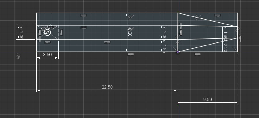
with the base extruded 1.2mm and the top extruded 7.1mm. The pointy "triangle" end was mirrored, and the entire length when done and adjusted was 36mm.
These didn't have a clip or a button protruding at the bottom to help "snick" the connector into the plastic base's hole, but then I found the tolerances too tight to slide them in anyway, unless there were some kind of spring mechanism to the clip. So, I chose to make the connectors easy to print, and I really cared, I could glue them into place. I ended up printing about eight of these.
3. S.C. Ruffey bumper

The cars come with circular bumpers at each end. One of those on the S.C. Ruffey car was severely bent, so I ended up breaking it off and re-glued it with CyanoAcrylate glue. That worked well. It's an area of the car that would only be under stress in a thrifting bin, not during normal operation.
4. Train car coupler springs
Each car has a latching connector that swivels left and right, and also bends up and down. Many of these were broken.
The mechanism basically relies on a spring made out of plastic. My initial solution was to use a rubber band, but eventually I designed a simlar plastic spring. Mostly, this was just a challenge to see if I could make one.
This is an example of a broken spring on a car.

This is the replacement "spring".

It's based on this design:

The sketch for that looks like this:

Given the sketch, I used a "square pipe" operation along the curves to get the more challenging part of the piece built. I chose a square pipe as opposed to a cylindrical one in order to avoid 3d printing problems.
The curves were initially created using a bunch of circles, and then I trimmed away the arcs that I didn't want.
The central part with the screw hole is extruded 2.1mm. The peg is extruded 2mm, but could be even smaller as it barely fits into the hook hole.
The challenge with this piece went further in that you have to be careful about thickness generated by your 3d printer. You really want the curves to be a single line of filament thick. If you have two lines, it gets too thick and inflexible. After exporting this piece in .STL, I would load it up in PrusaSlicer and check to make sure what it was doing, and then iterate.
Here is the spring, mounted on the car. You can see how it bends from the mounting plane in order to slot into the hook's hole, and on top of that, it has to be able to bend left or right as the car moves.

The problem now is that I printed these out of PLA, and that gets brittle in a short amount of time. Eventually, it breaks, like this:

So my next steps: re-print these in ABS, try "welding" the original springs in cases where I have them, and/or try to rebuild the whole car-to-car connector mechanism so I don't have these funky hooks.
5. Thomas - eyes
Thomas arrived a little scuffed up. His eyes were poked in. His top was missing. And he was missing the "lantern" on the front right.
I also didn't really know how Thomas worked, electrically.
In order to fix Thomas's eyes, I unscrewed the base from the top, and found that each eye was just plastic semi-sphere connected to an arm with a funny rectangular "hook". Since I had opened up the machine, it was plain to see that the train had some geared motors -- one to move the wheels, and another for the eyes. I presumed they were DC motors.
With some patience, I was able to align the eyes while re-assembling the top and bottom. That's just physical alignment, nothing special.
6. Thomas - power
After some reading I figured I was missing a 16 VDC variable power supply. Ideally, that would have a reverse switch, too. I noodled on this quite a bit, thinking I'd make a 555 timer PWM controller for it. Some sites say PWM works on some trains, but some others have electronics (noises, smoke, etc.) that don't play nicely with PWM. For this train, it's just engine power, so PWM would work.
I couldn't find my 555's -- I know they're around here somewhere... -- so I ended up just using a lab bench power supply to get the train moving. I ohmed out the pins, and found that the 1/8" stereo connector was only using two of its three pins. The tip was not connected. The middle and "barrel" (the ring closest to the wire end) were. I have the connector set up such that the power supply is outside the track oval, and that means I can use ground on the barrel and V+ on the middle ring to go forward.
I just used alligator clips to connect the power supply to the 1/8" plug. Some day, maybe I'll rip an 1/8" jack out of something, and make a proper connection with a DPDT switch so I can have movement in reverse without messing with the alligator clips.
With around 6V power, the engine ran! It was a little squeaky, so I dabbed a little sewing machine oil at the points where the train arms connected to the wheels.
7. Thomas cab
Thomas was missing his cab front, back, and roof.

Fortunately, there are slots that the front and back walls can fit into. Calipers provided a good idea of the distance of slot bottoms to the roof level.
For each, though, there are round portholes and it wasn't as easy to figure out how to position those. What I did was find a head-on view of the train on the web. That gave me rough proportional distances and sizes, so I could figure out reasonable porthole dimensions and positions. That also gave me a decent idea of how high to make the top arch for those pieces.
The next problem was that the front wall would run into the cylindrical tank of the engine. The good news there was that the tank's diameter was pretty cleanly measurable on the original, and using some proportional positioning, I could figure out its placement with respect to the roof height.
This is what the model looked like for the front and back walls. I did the front wall first, and then copied it, and extended it downward (without the tank arch) to form the back wall. Each is extruded to 1.6mm thickness.

This is the sketch of the front wall

A few corrections on this could be made. The front wall's tank arch is a little shallow, so the piece tips a bit. Also, both front and back would have been modeled better with the right and left side walls taken into consideration, so that the roof would have had some overhang.
Both pieces were printed flat on the 3d printer, and the face that met the heated bed was used as the outside, since it came out smoothest.
The front and back walls were painted with Testors light blue enamel paint, blended with some dark blue paint. But, I didn't notice that the light blue was flat, where I should have had glossy; and the dark blue paint was acrylic instead of enamel. It's close, but not perfect.
The front, at least, is supposed to have yellow trim around the portholes. I used Testors light yellow enamel for that.
I printed another circle to go in the circle of the portholes, and added a 9/32" hole in the middle of it. The disc went into the porthole, and then the whole thing went onto an old record player. I got that spinning at 33-1/3 RPM and gave it a few coats.


In retrospect, I would have been better served to have made a separate porthole trim piece, printed it and painted it separately, and glued it into the front wall's porthole. That would have made for much cleaner painting, and of course dimensional accuracy (compared to me, holding a paint brush).
8. Thomas roof
The roof piece was modeled after having created the front and back walls. Those gave me the dimensions of the top arch. The head-on picture from the internet gave me a sense for thickness.
Oddly, I don't have the 3d model for that part any more.
For 3d printing, I printed it vertically, so that the layer lines would go horizontally (port-starboard relative to the train, lowest layer in back, highest layer in front) with supports. It printed well, though the area where were supports ended up wavy and ugly. No matter, that part is hidden behind the cab's back wall.
I sanded the roof top down quite a bit, and then gave it several layers (thinned) of Testors glossy black enamel.
Prior to sanding and painting, things looked like this:

9. Thomas lantern
After I was all done, I thought I'd build the lantern that was missing at the front of the train.

Here are some iterations of prints that I did for the lantern.


There were holes on the original train that presumably held the old lantern in place. In my v1 rendering, I just had holes in the base of the lantern, and thought I'd have screws coming up from underneath to hold it in place.
However, the base of my lantern was so thin (2mm extrusion) that I would have a hard time getting a screw to bite into the plastic and hold, and yet avoid poking through the top.
My v2 lantern used the same model as v1, but I just added pegs going down, and sliced it with a plane from left to right. That allowed me to print both halves and glue them together. In doing that, the holding pegs were also split in half.
That looked good and functioned pretty well, but the seam was quite visible.

But I wasn't satisfied with that. I decided I really wanted it to light up. I re-modeled the lantern with the idea that I'd have an LED inside, rather than having the sphere. This is what it ended up looking like. Compared to v1, it obviously has a hole cut out for the LED, but also a more attractive side structure, and it's thicker in front. Why? Because in its original form, the front was so thin that light would shine through the plastic.

The based of the lantern has some slots that lead to the points where the holes reside.

From there, I took an LED and carefully bent its legs so that they fit in the bottom slots. This was tricky, because I had to make sure the right amount of LED bulb was visible within the lantern, and the wires slotted in properly, and then were bent so that they would go into the holes in the front of the train.
This is what it looks like, all mounted up.
.jpg)
Once I had that figured out, I moved on to the electronics part. The main part was a little circuit board that came from some kind of solar-powered light. It had a latching push-button switch, and a Q5252 circuit board on it, and a 4 ohm resistor.

The Q5252 is a cute little thing with very poor documentation. Basically, it appears that it can be powered from 0.5v to 1.5v, and then it provides a boost mechanism to get to higher voltage, if you attach an inductor. I didn't have an inductor, and there wasn't one on the board so I left that off.
The Q5252 also provides contacts for connecting a solar panel to charge a little Lithium Ion battery. The solar panel was missing, or I'd already snagged it for some other project. I de-soldered the battery terminals, and wired those to a AA battery pack so that a single AA battery could power it.
In an isolated test, I verified that in that shape -- no inductor, no panel, single AA battery -- I could switch on an LED and leave it on safely without burning it out.
As such, I replaced the LED output of the board with wires connected to a screw-down terminal block. I then added wiring from the lantern's LED legs and clamped them to the circuit, and tested it. Satisfied with that, I 3d-printed some clips to hold the wiring, glued the lantern and clips in place, and then just put blue tape over the remaining wiring so that the battery pack and circuit could reside in the cab.
Here's what a clip looks like. The shorter flat glues upward to the base of the train. The slot size is specifically designed for the 24ga silicone-coated wires that I got for another project. They measure out at about 1.6mm OD but can squish down to around 1.45mm. As such, the entry point (top, left, in image below) has to be wide enough for the wire to get in, and the slot itself is a little tight so it holds on to the wire nicely.
While it'd be nice, visually, to have chamfered or filleted corners on this, I just left it as is. I checked against how it'd actually be rendered in PrusaSlicer to make sure it'd be sturdy. Having chamfers or fillets sometimes makes for more retractions and skips in the print.

This is what the clips and wiring look like under the engine (laid down sideways).
.jpg)
I chose to send the wiring up the side of the engine, rather than drill holes. I also chose to use the AA battery pack to simplify the electronics. If I were to run the light off of the track power, I'd have to contend with a +/-16VDC voltage swing -- so... rectifier, step-down, etc. -- and then drill a hole somewhere in the body to feed wires through. That's all doable, but at this point I just have some things glued on, and no holes drilled.
Here's a side view, where you can see the battery pack, etc., ingloriously lumped into the cab.

And here's a view with the light turned on.

Done for now!
Here's Thomas running at about 10.5v. He has a tendency to de-rail currently, probably because several of the PLA coupler springs are broken. Or, maybe he de-rails because he's trying to stay true to the original TV series.
Will I sell the set? Probably not. It's nice enough to think of taking it out each Christmas.