I was presented with a wonderful little 3018 ProVer CNC mill a little while ago.
After a test run with it, where it cut really clean isolation channels for a PCB, I figured I could move on to doing something artistic.
I decided to make a "grayscale" image of a dog by drilling lots of holes in a black surface. The black surface I found was a "chalkboard" from the $1.25 store. It's basically 3mm pressboard with some kind of plastic surface.
The variations of light would be achieved by using different size drill bits: 0.6mm, 0.8mm, and 1.0mm.
Here's an example dog:
In order to get a good result, I did some Photoshop magic to eliminate details:


and then rotated the image to match the layout of the physical material that I'd be drilling:


Coding
To reduce the image in resolution and color space, and to generate gcode for drilling, I used a combination of Python 3.9, Python image library (PIL) and numpy. For a coding environment, I just used IDLE.
Hexagonal pixels
My thought around how to lay out the drill holes was to use a pixel pattern comprised of equilateral triangles, rather than the typical "square pixel" kind of layout we're used to.
The holes ended up being 1.4mm apart so that if I had several 1mm drill holes next to each other, there still would be enough "wall" remaining to prevent breakage.
If I were to have a traditional X/Y grid of pixels, each hole might be 1.4mm apart along X or Y, but along the diagonal, a hole would be 1.4mm * sqrt(2) from its neighbor.
Instead, I chose to use equilateral triangles. That means each hole center is 1.4mm from all six of its neighboring holes.
To achieve this, I could march 1.4mm along a given "scanline" on the X axis. As I'd move Y along, it would move that step amount (1.4mm) * sqrt(0.75). Do some geometry and you'll see where that came from. On every other scanline, X's starting location would be half of the step amount.
Each drill point could then be mapped to the original image resolution, or vice-versa.
Averaging
I take the center point of the mapped pixels in the original image, and grab a square of pixels from it. Then, I use numpy to logically "AND" that with a (255,255,255) circle whose diameter is the same as the square. It's not exactly the hexagonal pixel it should be, but it's close enough.
Once I'm done with that, I have only a "circle" of the grabbed pixels, and I can just compute an average of the non-black pixels.
Since I'm dealing in grayscale values -- but with an RGB-type image -- I end up with pixel values like (5,5,5) or (142,142,142). All the R, G, and B values are the same for each pixel, and each is in the range 0..255.
From there, I make a crude attempt at mapping the 0..255 values to the drill bit size that would emit a corresponding amount of light. I'm doing that very crudely right now, just dividing the 0..255 value by a divisor. The higher the divisor, the darker the result, and vice-versa.
Visualization
I added a few things to help visualize what was going on. At first, I printed an ASCII character to represent the darkness and lightness of the holes as they were being generated. These wouldn't come out in a triangular/hexagonal grid, but would give me a rough idea if I was getting the right result. Also, it would be more vertical than horizontal because of how our fonts work, typically. This is an example of some of the output:
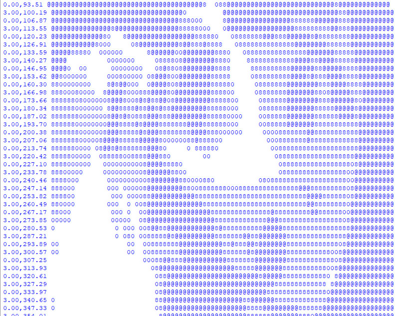
(The numbers on the left of each line were just confirming to me that I was alternating X positions on every other scanline.)
Image rendering
Once I was satisfied with that, I added code that would construct an actual image, creating white circles of appropriate size for each drill point. This is a more accurate representation of what the physical result would be.
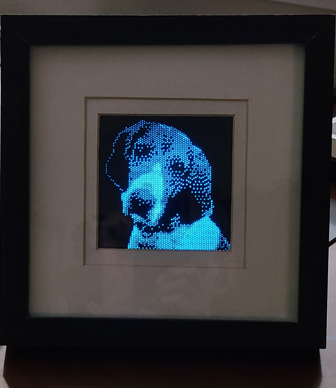
The initial implementation did straight-up averaging and no error distribution (dithering). I found that generally a lower divisor would give a better result. This image is no dithering, divisor 3.65.

Dithering
With a little bit of coding, I added dithering, which would distributes the light energy error to neighboring pixels (one to the right, and two below). "Error" here is defined by the amount of light coming out of a given hole (math out the PI*r^2 of each drill bit) compared to the average light value I computed for the average of the pixels in a chunk from the original image.
Each of the right, down-left and down-right pixels receives 1/6th of the error energy, so it's all done in one pass from top to bottom.
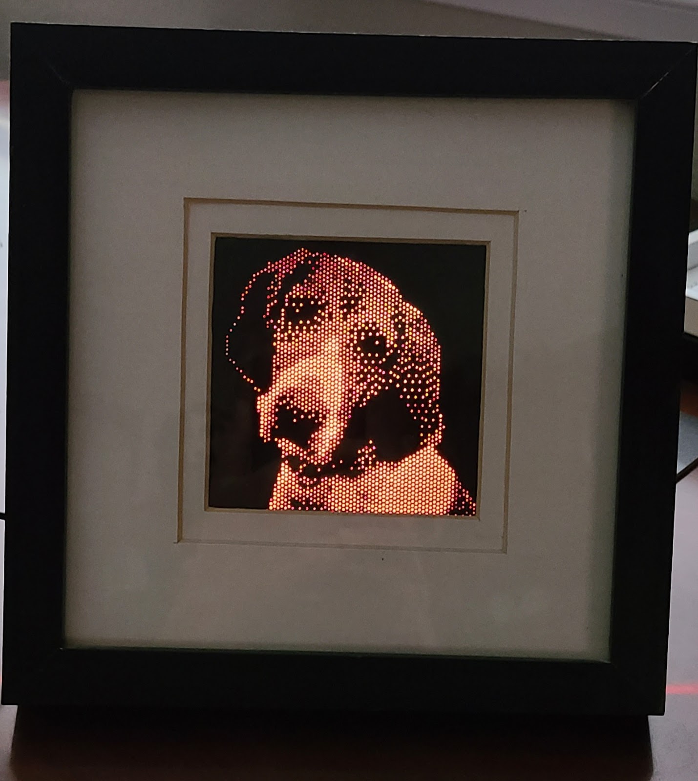
The image below has dithering turned on, 1/6th distribution of error to neighbors, and a 3.95 divisor.

The overall result from dithering is noisier but, in ways, more detailed. You can see a little bit more detail in the dog's nose, ears, and chest "coloring" with dithering turned on.
Satisfied with the simulation, I did a simple conversion to gcode. As I would draw each dot on the simulation, I would add the location to the appropriate drill bit's set of coordinates. So, each drill bit gets its own array of places to drill.
I then iterate. Each drill bit gets its own gcode file. I then walk through each location and issue the appropriate commands to lift the milling head, move, descend slowly to the surface, and then drill through the material.
I thought about making the code a little smarter about nearest neighbor computation to reduce the travel time of the milling head, but decided that's not worth the effort. I can just let the mill robot its way through, and perhaps it makes for a more accurate result if I'm primarily moving left to right. (Backlash by doing lots of pos/neg movements might make the result wiggly.)
Milled result
The milled result is pretty darned good. The only real problem is that the surface of the "chalkboard" has a tendency to tear, so I ended up having to use a Sharpie to blacken the pressboard where the surface was lost.

Lighting
While the initial result was pretty cool, the better result comes from backlighting. Here's what it looks like with just monitor white behind it.

Shadow boxing and more lighting
I headed out to the nearby Goodwill and found a few shadow boxes that I could repurpose. That would serve as the frame. It was a cheapie home decor item with some kind of thing that would seem cultural inside. I used my hot air gun to melt the hot glue that held the back in place.
I also had had the good fortune to have found a Lampeez "3D Lamp" on a prior thrifting adventure. Those lamps just edge-lit acrylic with a drawing on top, laser-cut (apparently) to the borders of the drawing. They're not really "3D", in my opinion. They're about a 3D as my dog chalkboard.
The Lampeez base has interesting stuff in it. It's powered by battery or USB, and it just has a board inside that does some magic and turns on some SMD LEDs. There's a touchless switch mechanism that uses a single wire like an antenna. Newer ones come with a remote control and the board sports an IR receiver.
I took the Lampeez PCB and desoldered its touch sensor and IR receiver, and then added extension wires to each. The touch sensor wire's end is connected to a small piece of metal -- just a 1" x 1" piece of aluminum foil is all it takes -- in order to work again.
I taped a sheet of white printer paper on the back of the dog chalkboard to help diffuse the light. Then, I mounted the Lampeez PCB to the back panel of the shadow box. I cut a little hole in the back of that panel to allow the USB power line to come out. (If someone wants, this could be replaced by battery power and a switch, instead, but you'd have to make it rechargeable.)
The aluminum foil antenna is just taped to another place inside the back panel. A touch on the outside of the panel activates the switch, and pressing and holding there will turn off the device.
The IR receiver is taped to the back panel, and faces the front of the box. As it turns out, the holes in the dog chalkboard let the remote control signal through to the IR receiver, so that works like magic without have to add a special hole just for that component.
The end result currently looks like this. It's presenting a square result right now, just because that's how I found the matte of the shadow box. I might change that up so more of the dog can be seen. The remote control lets me set different colors, or go into a mode where it fades across different colors.
Before and after
"Pixel" shape variations
The original code just drew a circle for each chunk of original image pixels that would be averaged.
I tried a few alternate implementations where I draw a hexagon -- either with flat top or flat sides. In theory, that would provide a more accurate representation of the original data. But that doesn't necessarily mean you get a more aesthetically pleasing result.
What it means is that along with choice of physical size, dithering, and divisor (aka gray-to-bit size mapping), the chunk pixel shape can provide more options for how the end image will be built.
Here are comparisons. In order, they are pixelShape = circle, flat-top hex, flat-side hex. If you look closely, you'll see differences in the dog's right eye, brow, and nose. If these were overlaid, you'd see many other subtle differences.


