I had the good fortune of finding a Cube Pro Duo for a low price, used. The prior owner said the motherboard was blown, so it had sat unused for a while. Even so, it wasn't all that dusty. We lifted all 75 lbs of it into the back of my car, and off I went.
There are lots of videos out there about the Cube Pro Duo. It's a big, heavy machine. It actually turns out that The Claw was built using the top of this same kind of printer, so I'm familiar with its innards.
I was able to slide it down a makeshift ramp to get it out of the car, and then put it onto furniture moving "glides" to move it into the garage.
The disassembly started with the removal of the build plate (just lift off), top panel (just lift up), and back panel (pull away -- it's held by magnets). One of the magnets lost its adhesion, so be careful to make sure you have all of them.
My goal at this point was to just get the metal frame out of the enclosure. I couldn't really address the electronics issues until I got the cube frame out. (The power supply, motherboard, and other things are at the bottom of the cube frame.)
Step 1, of course: totally unpower/unplug
the machine, and allow caps to discharge before proceeding.
I was able to tip the machine over on its back (onto a soft surface), and remove the screws holding the feet on the bottom of the enclosure. The screws holding the feet in place also hold the cube frame to the bottom of the enclosure. The feet themselves could just be pulled off after the screws were out, though one of them gave me a bit of trouble, because it had been mounted so tightly. Fortunately, there was no glue involved.
This is the back side of the machine with the back panel removed.

There's a "Back, Inside Acrylic" panel (BIA) that houses clips for keeping sheathed cables and Bowden tubes organized The BIA is bolted in place with a number of metal clips. The clips then attach to the back edge of the enclosure. I removed all those bolts that connected to the BIA, and loosened the bolts at the edge to rotate the clips out of the way.

One aspect of the Cube Pro Duo is that there's a lot of acrylic involved. The acrylic parts can be broken pretty easily.
I removed the screws at the ends of the metal bar that serves as a cross-brace for the BIA.

I started to remove the bolts that hold the BIA to the bottom posts of the steel frame, but realized it was too early to do that.
In order to get the back panel off, I would have to unhook all the connecting cables. I started by pulling off the three plastic clips that held the Y axis cable sheaths in place. These could just be pulled and wiggled off. If they get hung up on the sheathing, you can reach in from the top and free them.


Then, I removed the two screws and nuts that were holding the drag chain to the BIA.

I finally unscrewed the last bolts that were holding the BIA to the frame. This would allow me to lean the BIA outward and undo the remaining clips. Or so I thought. Be quite careful at this point. It'd be really easy to get the BIA corner caught up somewhere, lean it outward, and crack the acrylic.

There is a small PCB at the top of the BIA. I think that PCB is there just to hold a thermistor for measuring the enclosure temperature. I started to remove the
nuts/bolts that were holding it in place, but that was a mistake, so
don't do that.

Instead, if you lean the BIA outward, you can reach the clip that holds the signal cable to that PCB. Unclip that.

The BIA is still not free, because it has clips that hold onto the sheathed cables and Bowden tubes. I thought I could just pull out those clips in the same way as I had done for the little plastic clips earlier. However, the Bowden tubes go through holes, not C clips, so to get this apart, I would have to thread those tubes through the holes.

The Bowden tubes were connected to a screwed-on ferrule along the Bottom Acrylic Plate (BAP). Those would allow a proprietary filament box to feed acrylic into the tube from a known point. The ferrules were zip-tied to the bottom, so I cut those off. (Pardon the bad photography here. The shadows make it look like there's a weird shape to the BAP acrylic.)

I then threaded the tube+ferrule end through (below) the BAP, and then unscrewed the ferrule from the Bowden tube.

I then threaded each Bowden tube through and out of the BIA clips. (Note: even though it's a dual-extruder machine, it's set up to accommodate three extruders.)
There was a lot of bending and kinking of the tubes at this point, which was uncool. I'm not sure if the bends were so bad that I will need new tubes whenever/however I reassemble it.
With the Bowden tubes out, I could gently pull the sheathed cables out of the clips, remove the clips themselves, and take off the BIA.
I wasn't sure what to to do move the frame next.
The following things need to be done:
Where possible, unplug the stepper motors. It helps in these steps to move the printer head carriage and Y gantry out of the way and it's best not to risk having current flowing back to the motherboard. (In my case, assuming the motherboard truly was blown, I didn't really care, but did it anyway.) It also helps -- but gets greasy -- to manually turn the Z axis threaded rod, thus lifting the build plate high and out of the way when needed.
Remove the upper bolts holding the power switch shield. That shield holds to the side frame, and gets in the way of sliding the steel cube frame out from the enclosure.

Remove any remaining bolts holding the cube frame to the enclosure sides. If I recall correctly, there are three on each side.

Remove the two lower bolts (one on either side) that hold the power switch guard to the enclosure side, remove the switch guard itself.

At this point, the frame is mostly moving separately from the enclosure. There are just a few things in the way.
There's a USB and SD card connection on the left side at the front of the enclosure. It's tricky to remove these. They can't just be unclipped, because the upper board (USB) blocks removal of the lower board's (SD card) wiring.
What I did, which may not have been right: first, unclip the upper board cable. Then, with some gentle nudging plastic, the upper board can be pulled inward from the enclosure side and removed.

This reveals the lower cable, which can be unclipped. You can leave the SD card PCB in place.

In retrospect, it appears that the whole assembly could have been unclipped from the side of the enclosure with the wires in place. It looks like the original assembly would have had the worker push this into place, clipping onto the metal (elongated octagonal) clip. So, maybe by pressing gently on that top tab, the whole thing might have pivoted inward.
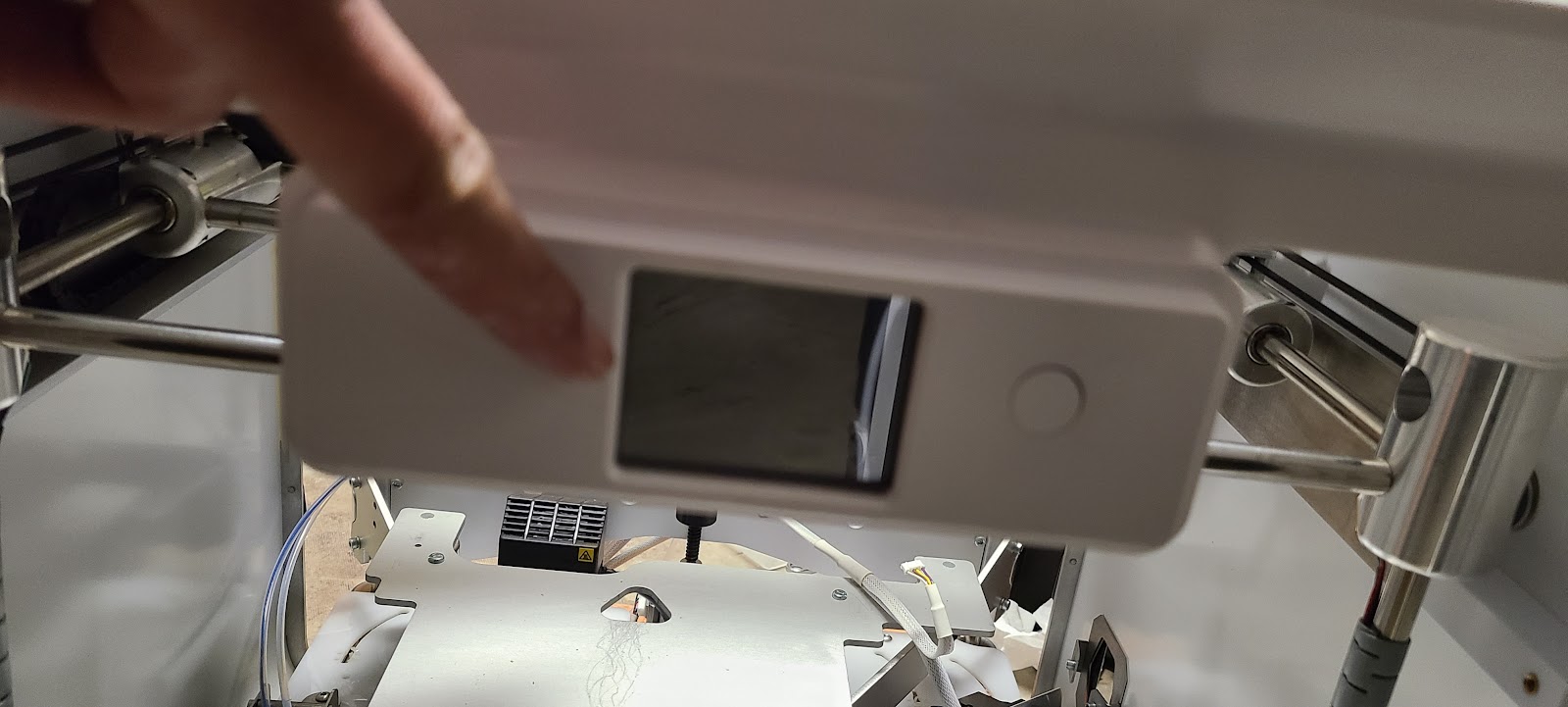
Finally, there are a few more cords to be unclipped, the main one being the front panel display. The wire bundle that goes to it is neatly hidden in a wire management thing. But to unclip the front display requires disassembly of the display. If you're looking to use this in the future, beware of ESD.
This is a not-so-great picture of the front display. It's a little LCD panel and a single button.
On the inside of that, I took off four screws...

and then, with the PCB exposed, removed the screws that held the PCB (and display) to the front plastic

and then I was able to unclip the wiring from the front panel PCB.

All the wiring of the USB/SD Card and front panel displays has to come out from a nice, cable management thing so that the cube frame can be removed. I can't remember exactly how that part worked, and kind of don't care because I won't be reusing those electronics.

Success! I was able to slide the cube frame out from the back of the enclosure. It was still quite heavy. You can see here that I used a few pieces of redwood fence board scrap to support the back of the cube as I slid it out. Otherwise, the weight might have crushed the bottom edge of the back of the enclosure.
A note on lifting here, too. I would typically lift the cube frame using the front and back upper bars. Avoid lifting with the "Y" axis bars (left and right), because they need to stay lubricated and there are belts and such that you don't want to damage.
In the picture that follows, you're seeing the cube frame in the foreground. The drag chain still holds all three sheathed cable assemblies and Bowden tubes. The view is from the rear of the printer. At the top left you can see the empty enclosure.

With all that done, I'm not sure what the resulting weight was, but it was still heavy. I slid it onto a furniture dolly, and moved it inside for further work.