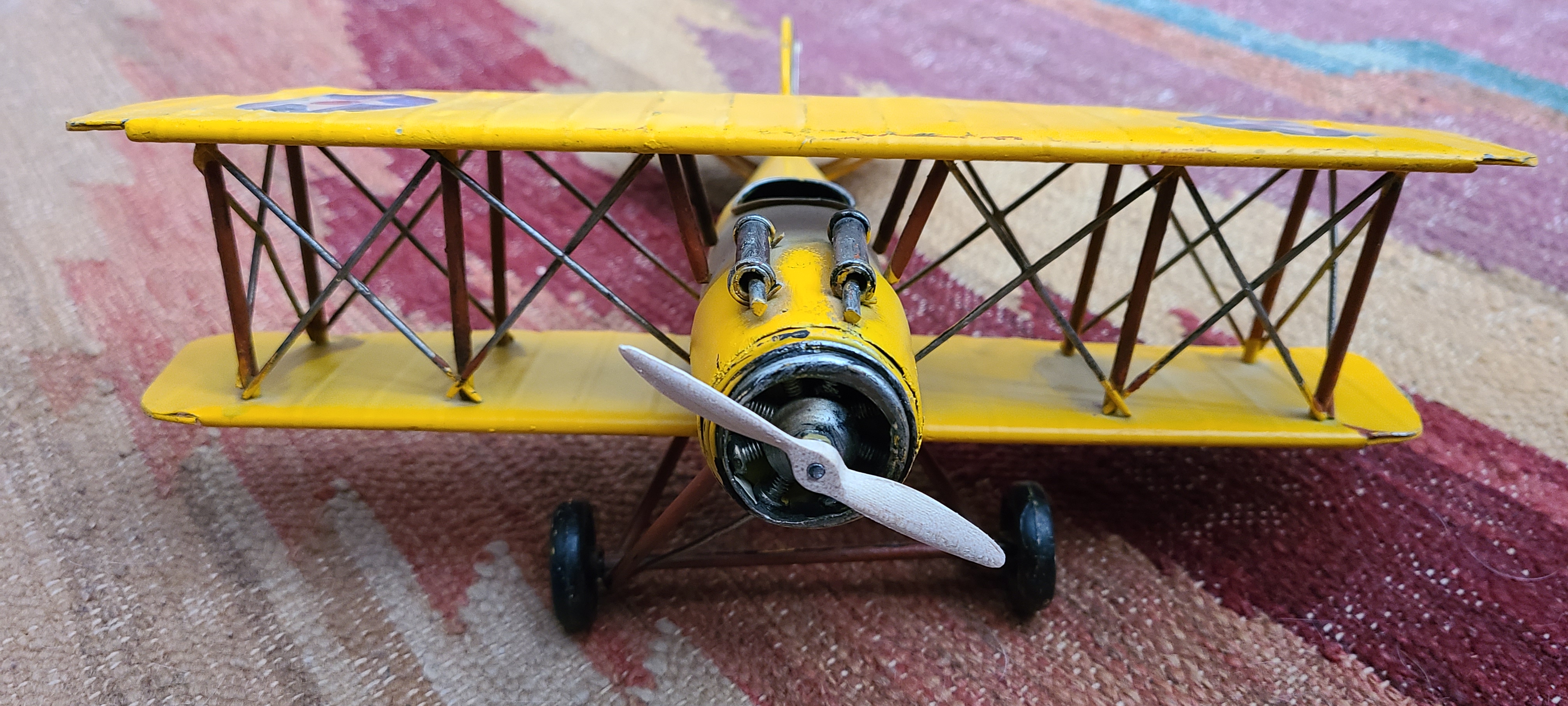
I got a pretty cool (well, I think it is) metal biplane from the thrifting bins the other day. It's yellow, and labeled "HG41" and even has a security tag on it, so it must be super valuable. 😉
When I got it, some of the struts were bent, and some of the edge sheet metal lips were out of sorts, so I nudged them back into place.
The biggest problem, though, was that it was missing its propeller.
So, I took it upon myself to attempt milling a propeller for it. I could have 3d-printed one, but didn't want to deal with sanding down lots of supports, since I only have an FDM printer.
Modeling
As a starting point, I found a propeller somewhere out in the STL universe, and brought it into Fusion360. It started as an IGES file. Fusion360 allows you to just open that kind of file, rather than importing the point cloud into an existing model.
I'd downloaded the file as "push-propeller-1.snapshot.11.zip" and within there was a Prop.IGS file.
So... that's File > Open > Open from my computer... > and then navigate to find the Prop.IGS file.

IGES to solid body
Immediately after loading it, you can do a Design > Solid > Inspect > Section Analysis and you'll see that it's not being treated as a real body.

To make it into a body, go to Design > Surface > Modify > Stitch, and then window-select the whole propeller. Leave the Tolerance at 0.1mm and hit OK. Now, if you do a section analysis, you'll see the banded lines that indicate it's a solid body.

You also will see in the Navigator area that there's a Prop > Bodies > Bodynn object that's been created, and wasn't there before. Prior to that, it would have been Prop > Bodies > Unstitched (nn).
Scaling
I looked at some pictures of biplanes online, and with some math, I figured the propeller would have to be about 70mm long in order to look correct on the plane. I used "i" to get information about the current length of the model, and it reported back at 294.753mm.

To scale it down, I'd need a factor of 70 / 294.753, which is about 23.75%.
So, I just did Design > Modify > Scale, and entered .2375 as the scale factor.
With that, I then re-did the "i" information measurement, and found its tip-to-tip measurement came back at 70.001mm.

I also then measured from one face of the hub to the other, and got 4.025mm. I checked that against the propeller spindle on the plane, and found that that would work.

The hole for the spindle in the model measured out as having a diameter of 1.425mm. However, the physical plane's spindle was a little more than 2.9mm. I added a sketch, and created a new hole.

That was all that was needed for the modeling / design side of things. I've been told there are propeller generators / plug-ins that I could use, but I just used the existing model on Thingiverse.
Milling
Milling something like this gets complicated, because there aren't great places to hold the work, and it has a lot of curvature on both sides.
After waffling on the "how" part of this, I decided to just cut the propeller out of good wood.
I modeled the stock for the propeller as 4.025mm x 8mm x 100mm piece of wood to start.
I had a stick of 3/4" x 3/4" maple laying about, and cut a chunk of that off. I then roughly band-sawed it in half, lengthwise, to get closer to the desired 4.025mm thickness.
After that, I used F360 to Manufacture a surfacing operation to bring it to 4.025 mm thick. (I don't have a planer, and besides, it's a really small piece.
For this operation, it was simple enough to just double-stick-tape the stock to my wasteboard. One side was already quite flat. The bandsawed edge was facing up. I just ran the surfacing operation with 0.2mm steps to get it to where I wanted it.
I used the "hole" sketch from earlier, and drew a centered rectangle around the propeller to define the stock. I added extra room so that I could put fiducial holes on each end, 4mm inside each edge. The rectangle was 100mm wide, and 19.05mm deep (i.e., 3/4 inch).

(Note: the left-side hole is "19.05/2mm" from the bottom edge, and 4mm from the left. There are lots of ways to do that. I also just made a line down the middle, and then mirrored the circle to the other side.)
I extruded it as a New Body with 4.025mm thickness (based on measurements taken earlier).

and then added 1/8" (3.125mm) holes. Having actual holes is useful when later using the Manufacturing functions to drill.

In the Manufacturing area, I started with the Setup.
Machine: Genmitsu ProVer 3018. I had already set this up in some earlier project. I think the main point here is that it's pre-configured to make the post-processing handle the G28 function the right way.
Operation type: Milling
Work coordinate system
Orientation: select X and Y axes (and adjust pos/neg direction afterward)
After choosing X and Y axes, I went to the Stock tab, and chose to dimension the stock based on the solid block I'd defined earlier. This can have its drawbacks, though, if you choose to modify the model later on.
Then, back on the first Setup tab, I chose to set my origin as the bottom (lowest Y), left (lowest X), upper (top Z) corner. That main thing here is that I'm defining Z origin as stock top.

Lastly, to specify the model, I selected the option in the dialog, and then clicked on the propeller body in the navigator. That's more easily done in the navigator than in the viewport because of how the stock and propeller are overlapping bodies.

Mill operation 1: Drill
Drilling
Select 1/8" drill tool
Spindle speed 5000 rpm
Geometry:
- Clearance: From Retract Height, 3
- Retract Height: From Stock Top, 2
- Feed Height: From Top Height, 1
- Top Height: Hole Top, 0
- Bottom Height: Hole Bottom, 0
- Drill Tip through Bottom: Yes
- Break-through Depth: 8mm (because I have a thick enough wasteboard for this.)


The way I do this is to drill a deep hole into the wasteboard that's 1/8" OD. That way, I can use an old, broken milling bit (1/8" shaft) as a pin for each fiducial hole, when I turn the board over.
Also, keep in mind the direction of the turn you'll be doing. I set up these holes along the midline of the propeller, so the intent is to flip the board along the X axis. It can be helpful to mark your stock with "top", "left", and "right" words so you remember which way to flip it.
Mill operation 2: 3d contour
I chose to use a 3d contour to hog out material.
Tool: 1/8" flat end mill
Geometry:
Machine Boundary: Silhouette
Tool Containment: Tool Center
Additional Offset: 0.1mm
Model: check
Model surfaces: select the propeller body
Include Setup Model: uncheck
Heights: again, 3,2,1
Bottom Height: Model bottom, 0mm
Passes:
Maximum stepdown: 0.2mm
Stock to Leave: yes, 0.1mm radial, 0.1 axial
Linking:
Uncheck Lead-In Entry
Uncheck Lead-Out Entry
Mill operation 3: Parallel
Tool: 1/16" ballnose end mill
Geometry: Silhouette
Tool Containment: Tool Center
Model: select propeller
Heights: 3,2,1
Top height: stock top
Bottom height: model bottom -- why? I'm not sure, but it works.
So far, with these three milling operations, we've created fiducial holes and milled out the "top" of the propeller without going over the sides. The Silhouette and Tool Containment settings kept things from cutting over the edge.
What I did at that point was: save a copy of the design to a separate project, flip both stock and propeller objects over, and then repeat the milling operations (minus the drill operation). So, you get two more flipside mills: 3d contour and 3d parallel.
When this milling is done, you still don't have a piece that will separate from the stock, and that's a good thing. To do the final edge cutting, I added one more flipside milling operation. I chose to make this a 3d parallel instead of a 3d contour. A contour would mill around the edge, potentially cutting the propeller out completely as it's going around it. I found that a 3d parallel would do more of a sewing machine movement allowing for more gradual removal of the connecting material.
Milling 4 = flipside 3d contour
Milling 5 = flipside parallel
Milling 6 = flipside edge cutout
Operation: 3d parallel
Tool: same 1/16" ballnose end mill we had in Milling Operation 5.
Machine boundary: Silhouette
Tool Containment: this time, use Tool outside boundary
Rest Machining: check
Model: select propeller
Heights: 3,2,1
Bottom Height: from Model bottom, offset 0.1mm
Pass direction: 45 deg
Direction: One way
Up/Down Milling: Down milling (not Both, not Up)
Multiple depths: check
Maximum stepdown 0.2mm
Stock to Leave check
Radial 0.1
Axial: 0.1
Here's what it looked like when milling.
Initial "top side" contour / hogout:

Flipside final parallel (edge cutting). Note change in hold-downs.

After all machining is done, propeller still attached to stock.

I used a hobby knife to cut very carefully around the edges, where the CNC hadn't already gone through.

And this is what it looked like after sanding.

The propeller shaft on the plane actually was a little messed up, probably because the original propeller got torn off. After a little filing, it got it smooth again, and the new propeller ended up press-fitting quite nicely onto the shaft.
Result

Additional notes
Well, based on a quick e-Bay search, it looks like this is the Curtis JN-4 Jenny Yellow S-02 Model Barnstorming Metal Biplane.
The pictures on e-Bay have a big ol' ugly propeller but maybe it's more authentic.
It looks like a real one can be seen at
https://www.militaryfactory.com/aircraft/detail.php?aircraft_id=980
and the propeller there is way fancier, having almost an ess curvature. But that's a Jenny-4D, so maybe things changed.
Another can be seen at https://www.cybermodeler.com/aircraft/jn-4/jn-4_all.shtml
and yet another head-on at https://www.cybermodeler.com/aircraft/jn-4/images/mof_jn-4_01.jpg
Given the last one, I'd say my propeller is of proper dimensions, but reversed! Mine is set up for a counter-clockwise motor rotation, but a real one goes clockwise (from the point of view of the pilot). Noooo!!!!
Yeah. I have to do it over again. But now I know how to do it. I'll probably re-do the mount points and change some speeds if I do it again.
Here's the curvy one. It's called a Scimitar propeller. What do you think the odds are that I'll find an STL of one of those?
https://www.historicpropellers.com/woodenpropeller-curtiss-jenny/
Mirrored and re-miilled
And so I gave in and just re-did the milling process.
This time, I bandsawed the material to about 7.6mm thick, so I re-did the surfacing to go from 7.6 down to 4.1mm.
I used the waste from last time's milling to figure out the positioning of the fiducial holes. I also made the stock a bit longer (the full 100mm, where prior it was closed to 90mm). Even then, I could probably really use a lot longer stock to allow for the clamps. Also, I could have changed the surfacing to have even more Y reach.
The F360 operations were easy. I did a "Save As" of the original project, and then added a midplane (along the long axis, XZ) and did a Create/Mirror of the propeller body. I renamed the new body as "propmirrored"

and then turned off visibility of the original propeller.

From there, I just re-computed all the milling operations to be based on the propmirrored model.

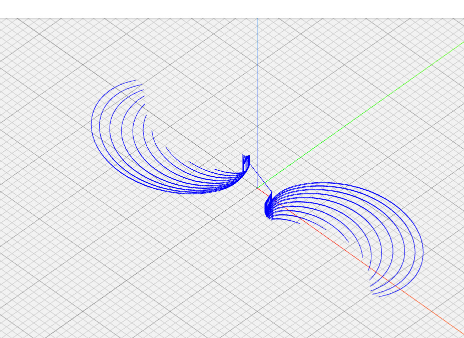
The sewing-machine-style edge cutting milling operation didn't work as well this time. That's probably a reflection (no pun intended) of how that last operation was set up for one orientation of the propeller at a particular parallel angle.
Here's what the not-so-great cut path looks like with the mirrored propeller.

You can see that there are a lot of cuts missing around the end points and about half of the hub isn't separated on +Y and -Y.
This is what it looked like for the edge cut on the flipped-material, non-mirrored model:

Note how the entire hub has cut points, and a lot more edge is covered.
What I forgot to do was to modify the Parallel > Passes > Pass Direction setting. I had left it at 45, and since the model was mirrored, I kind of had to mirror the milling angle, too. By setting it to 135, I got behavior similar to the original, but for the mirrored model:

Anyway, the not-as-great milling of the mirrored, flipped model's edge left me with way more connected material, and needed more aggressive hobby knife work.
End result shown here.


Remaining steps
- Maybe take a shot at re-computing the point cloud to generate a scimitar-style prop
- Staining
- Is the plane missing a rear wheel? I guess I have some 3d-printing to do.
An attempt at the scimitar-style propeller model
I looked at the IGES format of the propeller, and it's pretty cool but also quite complex. IGES has different sections of data, some acting as directories into entities, and then those entities are definitions of geometric things and modifications. Among the geometric items in this propeller's IGES file you find transformation matrices and various forms of splines and surfaces. In short, it's not conducive to having operations done on a per-point-within-a-point-cloud basis.
Instead, I went back to a simplified form of the gcode as the basis for mathematical manipulation. And, to further simplify that, I changed the roughing (3d contour) milling operations to be plunge-type, rather than helical. The helical ones would generate clockwise and counter-clockwise gcode commands, which would require generation of a gcode interpreter to get all the interim points.
A scaling algorithm based on an arc
The initial algorithm for doing the scimitar modification is based on this drawing, which I did in F360.

The idea is this:
The "propeller hub center" is the center point of the propeller.
The black line extending to the right is the X axis.
What I'm doing is mapping anything along that line to the arc at the top by doing a linear scaling of the points.
Assume there is a center point (cx,cy) halfway to the max X value of the propeller points. So, cx is half of max (x in the gcode).
Then, let there be a point (px,py) in the gcode. In this example, the conversion would only apply to positive px values.
Given the points (px,py) and (cx,cy), I can compute (just by similar triangles) an x-axis intercept point, (ix,iy).
Given the intercept at (ix,iy), I can figure out what the scaling would be to get (ix,iy) to stretch out to a point along the arc. The scale factor is the ratio of
(cx,cy)-to-(hub center) hypotenuse divided by.(cx,cy)-to-(ix,iy) hypotenuse
If I apply that same scale to the (cx,cy)-to-(ix,iy) delta, then I get a new point.
The same approach would be taken for negative (px) values but using the negated (cx,cy) positions.
The amount of curvature is influenced by the magnitude of cy. The closer cy gets to the X axis, the more pronounced the curve.
I already had some python code that would do a very rudimentary step-through of the gcode, and identify changes in x,y,z,f. I generalized that a bit further to convert plain x/y/z lines to complete lines.
For example, you could have
G1 X5 Y2 Z7 F333.33
X6 Y4
X3
I would internally treat that as
G1 X5 Y2 Z7 F333.33
G1 X6 Y4 Z7 F333.33
G1 X3 Y4 Z7 F333.33
At each line, I'd apply the transformation. Here's the original roughing gcode path, and below it is an initial result of the transformed roughing gcode.
 |
| front contour, original |
 |
| front contour, transformed, cy = -10 |
That looked interesting. But this is what the fine (parallel) yielded. Again, first the original, then the transformed version.
 |
| front parallel, original |
 |
| front parallel, transformed, cy = -10, attempt 1 |
Pretty good, right? But what's with those coarse steps?
There was a further trick in that the gcode points sometimes would stretch long, linear distances. So in the gcode example above, the "X3" line is stepping 3 full units from X6 to X3. Since I'm mapping things to an arc, I want incremental steps. I put in a section into the code that would look for "large" steps. If the movement from one point to another (based on dx, dy in model coordinates from one line to another) were too big, then I'd generate interpolated steps, and feed those steps through the same transformation, and do a final step as with any normal, not-too-large step. (NB: I'd do incremental steps, transformed in X and Y, but I also had to do incremental linear transformations in Z changes.)
With incremental stepping added for "long" steps, I ended up with a much cleaner result.
 |
| front parallel, transformed, cy = -10, interpolating |
Much better.
But now it's obvious that there's a shearing effect happening. You can see that at the center of the hub, the once circular hole and the hub itself are now elongated.
To highlight this further, I've attempted to create an animated gif, showing the results of values cy from ranges -10 to 45, along with the original image (which is, basically, cy = negative infinity).
Hopefully, this blog will support an animated gif...
 |
| front parellel, transformed, cy = {-inf, -45..-10} |
So now I'm back to being a little stuck, trying to figure out how to compensate for the shear -- which looks linear but really is probably radial -- without messing up the effect of the transformation.
Credit to ncviewer.com for gcode rendering, and Adobe Photoshop Elements, for screenshot, crop, position, layer, animated gif generation.
Switching to a revolve transformation
One of the problems with the scaling algorithm above is that it not only shears the model, it also resizes the blades.
I think instead I'm going to do something where I'll rotate the points clockwise by an increasing amount, ideally starting at 0 degrees of rotation at the outer diameter of the hub, and increasing gradually as the distance from center increases. That should leave the hub and center hole alone, preserve the connection points closest to the hub, and mostly preserve the blade widths.
I thought of doing a linear translation instead of the scaling I'm doing now. That also might work, but I think it would have strange artifacts near the center and tip.
The rotation transformation would probably be ideal if I were to compute an offset plane incrementally along the X axis, slice the model with that plane, and then rotate the resulting polygon (around the Z axis) to a new position. I'd have to leave it to some point stitching tool to get all the faces glued together again.
I tried the above, and ended up not doing the distance threshold. I also made the gcode un-rotate all points, post-transformation, by about 2/3 of the transformation angle, so that the model would stay mostly horizontal.
Here's the result, ranging from 0 to 45 degrees of "angle range", stepping 5 degrees at a time. What that means is that if the distance from origin to a point in the gcode is maxed out, it'll rotate 45 degrees. The closer it gets to the origin, the rotation gets closer to zero. The angle change is linearly interpolated.
 |
| front parallel, rotational transformation, angle=0..45 step 5 |
The effect is most evident at angles 40 and 45. Prior to that point, the original curvature of the "scoop" part of the blade still appears obtuse.
NB: I had to fix a bug here, too. Before using {:.3f} formatting in python, I was getting long doubles printed in scientific notion, such as this:
G1 X19.728884661664274 Y8.214719016486072e-05 Z-0.494 F700.0
G1 X10.049908419900351 Y-4.01997769143847e-05 Z0.265 F700.0
That wasn't working correctly in ncviewer. It would renders as if it were going to Y8.21 or Y-4.01. Chances are, ncviewer has it right (i.e., gcode doesn't support scientific notation), so I changed the code to print X, Y, and Z coordinates using 3 digits of precision.
I added a few other things to the program: recognition of sys.args[1] for the rotation angle, handling of the G2 and G3 commands and their I and J parameters.
A few other things. I had done a compensation anti-rotation of 2/3rd of the angle, just to make it look good, but I'm not sure how that will play with the flipped gcode. So, I chose to anti-rotate 100% of the angle, which is what's shown in the animated gif above. Note how the max tip point stays stable throughout.
I have to see how this works with the flipped gcode.
And then the next problem is that if I use 45 degrees -- and maybe if I use 45 -- then I think I'll be getting really close to the 19.05mm stock depth (Y range). That's not a huge deal. It just means I'd need a different stock source, something other than 3/4" square hobby sticks.
Oh, and the other really important thing to look at: I think maybe my animated gif above, ranging from 0..45 degrees, would end up milling things backwards again for a clockwise propeller. At a positive 40 or 45 degrees, the tip cuts through the air before the middle of the blade.
I think instead I really want -40 or -45 degrees. It's hard to visualize in gcode since these are subtractive milling operations. But I think it's really supposed to be a negative rotation for this transformation.
After some more comparisons with real scimitar propellers, I found that the -20 rotation is actually closer to the "real" thing. The scale of the blades is different from a real one, but the rotation is about right.
Another cut of the same propeller
I was about to cut a scimitar example, and then blew it. I selected the .nc files I'd originally generated for the mirrored version. Oops.
Well, since I went down that path, I decided to go all the way and finish the job. This one was made from pine stock. Here's a backlit image of what it looked like after all milling ops. Pretty cool that it's so thin.


