I got a Cricut Explore -- probably on old school v1, not an Explore Air -- while thrifting the other day. It didn't come with a power supply or any cartridges or weeding tools, but luckily the front panel still held a blade.
The model I have looks like the one depicted at https://www.cnet.com/reviews/cricut-explore-review/
After a bit of inspection, I figured I could cobble together an 18 VDC, 2.5A power supply for it (the specs, sort of, are imprinted in plastic near the power port) and build a generic cartridge for it (look for "George" cartridge DIY online) but that wouldn't get me too far. From the sound of things, I'd be locked into the cloud-compute way in which Cricuts are constrained now, and I wanted to see if I could make it work in some other way.
The machine is well made, and formed in an enticing way. There are plain old Phillips-head screws visible at the bottom, so it doesn't hit you immediately with that feeling of "we made special screw heads to keep you from doing stuff" feeling. But, besides those seven screws, nothing else is visible. Its overall structure was the more modern "we don't want to let you in here" kind of snap-fit construction.
The outer shell is white. There are two white "towers" on the left and right sides. There are front and top lids that open up to reveal the carriage. Inside, there are green towers on left and right, in-between the carriage assembly sides and the white towers. The top lid pivots on the green towers. The back is comprised of two white pieces -- one exterior, and one interior. The bottom is one big, green piece, and the front lid pivots downward at its front edge. The bottom part houses the electronics underneath the carriage assembly.
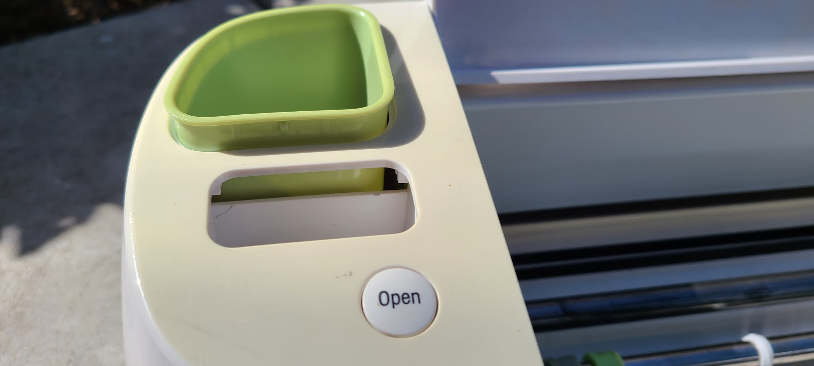
The left, white tower has a physical opening button that retracts two spring-loaded teeth, allowing the front and top lids to pop open. It also has a hole for plugging in a cartridge, and a little cup for holding tools or other things. Otherwise, it's just a plastic "skin".
The right, white tower also is mainly a skin, but houses the control panel. There are four buttons there, including the soft on/off button. It probably lights up when in operation. There's also a 16-position dial that appears to set blade pressure and/or speed, but it also has a "custom" setting.
Looking at the underside of the bottom, I saw four feet and seven Phillips-head screws. The visible screws were not related to the side towers, being too far away from them. I figured it'd be best not to touch them yet, guessing that they joined to the carriage or electronics, not the towers.
The four feet had rubber bottoms, and those hid four screws, which is typical for many devices these days. I peeled off the feet, and removed those screws.
But then I was kind of stuck. So much of the rest of the machine's joinery was hidden.
Deconstruction -- first attempt
Note: there's a second, and probably better, way to get into the machine listed below. Look for the heading, "Another way in". But it refers to these "first attempt" steps at some points, so please read on.
Initial opening: Left Tower
After some prying and wiggling, I thought perhaps the entry point would be through the decorative cup on the left side. That's meant to hold tools and other loose things. I was able to push one edge in from the "inside" by entering through the cartridge holder area, and then I could pry the rest out.
I thought perhaps the right thing to do then would be to remove a few now-visible screws, but that was kind of a red herring. It turns out I pulled out two screws that held the top lid hinge mechanism, but didn't get much further.
There was a plus side to removing the cup, though. Under it, they had taped some of the wires that control the paper feed motor, so I undid the tape to free up those wires.
I looked and looked, and eventually found a few inside screws holding the right and left white towers to the left/right green towers. I was pretty sure that they would have more than just those two screws holding things in place (along with the long foot screws that I'd already removed).
That led me to prying off and removing the white interior back panel.
Start: remove the interior, back panel
It turns out that that panel is cleverly snapped into place vertically. It has two hooks on each side that catch as you slide vertically onto pins, and then a snap-fit clip at the top that would nigh on impossible to undo without some force. Not knowing that, I broke the hooks and pins on one side as I pried it out. It's tricky actually removing that panel, because the tool carriage gets in the way, but it can be done more easily if you move the carriage to the far left.
Seeing how it's actually made, I probably could have pushed something into the crevice, pressed in from the sides to unhook the clip, and then slid the panel upward. Oh, well. Some breakage occurs.
Remove the white towers (and control knob)
Having the interior back panel out gave me access to a few more screws that were still holding the white side towers to the green side towers. I took those out, and then I was able to wiggle the white towers off. In the end, each white side tower is held by three interior side-screws, and two foot screws.
Along the way, while taking off the white towers, I had to remove the pressure adjustment knob -- it just lifts straight up. While taking the right tower off, I could then unhooked the electronics below, which amounted to simply uncliping a ribbon cable from the control panel's SMD header.
A first look at the XY motors
With the white towers removed, I could see the motor mechanisms for the X and Y axes.
Both sides use the same motor mechanism
Each side has:
- a DC motor, labeled MC385MG / 1030829
- a black, plastic shroud that compression-clips onto the motor mechanism
- a rotary encoder within the black shroud
- a gearing mechanism
The left tower holds the "paper feed" motor (the Y axis). The paper feed roller holds tension against the gears, using a lever and spring on both sides.
The tensioner for the carriage belt is also within the left, white tower.
The right tower holds the carriage motor (the X axis). That motor connects to the belt that drives the carriage.
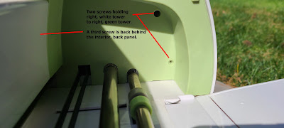
Both the right and left towers also hide the top lid hinge, which is the white piece shown at the top, right of the photo above.
The right tower also houses some kind of control port at the bottom. That has a spring-loaded oval door, which leads to some electronics. It is easy to lose or misalign the spring.
This is what it looks like when one of the encoder shrouds is pried up a bit, and pivoted around the wires.
Though I haven't yet done a full analysis of the wiring, it seems very likely that the four-wire bundles on each side are for the rotary encoder, and the two-wire bundles are for DC motor control.
What might not be clear without more testing is what voltage is needed for the motors, or what limitations there would be for the diode that lights the encoder.
Remove the top lid
The top lid has pins protruding on left and right through the green towers into white, goop-covered pieces. There are gears and a spring mechanism on each side that helps the lid open. The goop is both a lubricant and adhesive, sort of, that appears to help slow the rate at which the lid opens.
To get the top lid off, you have to remove three screws on the goop/gear hinges on each side. Pull those away from center a bit, and the lid can come out. I recommend screwing them back in place right afterward so you remember which screws go where.
If you reassemble this, you have to preload the springs a bit (rotation of the gear is counter-intuitive because of the gearing) with the lid in the open position before pushing the hinge back on the lid pin on each side. Otherwise, it won't auto-open. It's hard to verbally describe how to do the pre-loading, so I won't attempt to do that here. Also, don't overload the spring when pre-loading.
Remove the green towers and exterior, back panel
The next disassembly step was to remove the green towers. They were held onto the carriage frame by three Philips-head screws on each side.
After removing them, I was able to bend both green towers slightly inward at the front, and that released both of them and the interior, back panel in one go.
All that remains at that point is the carriage frame and the bottom.
Remove the carriage frame
The carriage frame is held to the bottom by the seven screws underneath the bottom (that screw upward from below) and four that screw downward, two on each side, from the carriage frame metal to the bottom plastic. Of the bottom seven screws, three connect to the back of the white plastic platen, and four connect to the metal frame.
The downward screws are a little tricky to get to. I had to detach the left tower's page feed tensioning spring in order to get to one of them. ** Update: it's entirely doable to remove three screws (and corresponding washers, lock washers) ot take the page feed motor assembly off. That provides easier access to the spring and carriage frame screw. It also eventually would allow for easier motor and encoder testing in isolation.
and the one at the back, right is blocked by the control panel ribbon cable.
Finally, there was one more downward screw at the front, right of the platen that had to come out.
With those all removed, the carriage could be lifted a bit away from the bottom, exposing the wiring and main board electronics. However, it couldn't be fully removed since many of the wires were taped down and/or clipped into channels to keep the wiring organized.
Detach wiring
There are duct-tape-like strips all over, holding the wiring down. I removed those carefully, slipped the wire around them, and then left the tape in place.
Once I did that, I could detach the wire connectors from their corresponding shrouds.
Here, I have removed the front wire connector. This is an eight-pin connector, with four pins going out either side. I assume this one manages both quadrature, rotary encoders.
This is a keyed, ten-pin connector that goes to the cartridge port.
Here, I detach the ribbon cable that connects to the right tower's user interface control panel.
Remove the carriage ribbon cable. This one controls the pen and cutter motors, and returns limit signals for the pen-up optical sensor, and presumably both up- and down-sensors for the cutter.
Unhook the remaining, taped motor wire
Detach the four-pin motor wire connector (at the right here, with the orange-grey and yellow-red wire pairs coming off of it)
One last step remains: unscrew the grounding strap. After disconnecting it, I just put the screw back into the hole, so I wouldn't lose it.
And finally, the carriage can come off of the bottom, completely, providing access to the wires without having the original control board involved.
The carriage
The carriage guts are hidden by a plastic cover. Now with everything else out of the way, you can see that it is held down by two screws at the back.
After removing the screws, the cover can be slid upwards and out of the way.
What we now see is two stepper motors, and three sensor wire bundles.
From the front, you can see the sensor mechanism exposed for the pen holder. It's just a fin that breaks a light sensor-emitter mechanism, probably, much like drop targets in electronic pinball machines, or limit sensors in H-P printers. (This mechanism also can be sensitive to ambient light, but being within the carriage cover, it's probably dark enough.)
The left side of the carriage is the pen holder, and it only has the one sensor at the top. It appears to be spring-loaded. As such, it's kind of acting like a solenoid. The motor can retract the pen until the sensor indicates the pen is up, and then the motor can release power to put the pen down (which is the normal position).
The right side of the carriage holds the blade. It does not appear to be spring-loaded, and it seems it has two sensors, one on top, and probably one at the bottom. The top one clearly can act as a limit switch. The bottom one, in combination with the motor mechanism, can allow motor-driven pressure control. That is, perhaps once it senses the bottom sensor is blocked, the motor can drive the blade carrier a few more steps down or up, depending on the dial setting.
Both stepper motors are the same, and neither has a rotary encoder as was seen on the X- and Y-axis motors. The ones I have are identically marked: RB STEP MOTOR / 11HA2210-14A / LOT NO. 140207. Since they're powered through a thin ribbon cable, I suspect they operate at pretty low power.
Right tower control panel
The right tower houses the main interface controls. On my Cricut Explore, that means four buttons (soft on/off power, up/down, C, and pause), and a dial with eight labels (Custom, Paper, Vinyl, Iron-on, Light Cardstock, Cardstock, Fabric, and Poster Board). With the interim dots, the dial really has sixteen positions.
The controls connect to a 16-pin ribbon cable, but only 15 of the pins appear to be actively used, based on observation of the surface-mount soldering of the ribbon connector.
The dial has five through-hole pins exposed. Assigning them numbers 1..5 with 1 being closest to the board label (and closest to the bottom three buttons), it appears 1 is common and the other four are a binary representation of switch state. Rotating the dial clockwise and continuity-testing, I got combinations like
b1111 (e.g., COM on pin 1, test pins 2,3,4,5 show continuity)
b1110
b1010
b1011
b1001
b1000
b0000
b0001
b0011
b0010
b0110
b0111
b0101
b0100
b1100
b1101
and then back to b1111
I'm assuming on the reverse (top) side, they have something akin to what you'd find in a sprinkler controller dial: rings with exposed copper/gold, and pins on the dial that connect.
These so-called pins 1..5 also connect directly to test pads on the control board. There are 16 of those, and they are labeld TP1 through TP16, but TP6 is missing. In order to continuity-test these correctly, you have to make sure the dial is in a b0000 position above.
1 = TP4
2 = TP1
3 = TP5
4 = TP2
5 = TP3
(From a circuit layout perspective, it makes sense that all five are grouped in this way. Also, the copper is wider for TP4, aka dial "pin 1".)
With five pins consumed for the dial, that leaves ten for the buttons. It's likely, too, that there's a light for the power button, so that would add two more lines needed. So I think it's safe to assume that each button has its own wire pair (i.e., they don't share a common ground, as is done for the dial). The vias don't serve well as test points, and it's not fruitful for me to look at the control panel in any more depth, so I haven't traced them all out.
Another way in
I reassembled the machine in order to take pictures and re-confirm the teardown steps, and I realized there is, perhaps, a better way to get into the device.
Initial state
(OK, this isn't totally put back together again, but you know this is mostly what it looks like.)
Remove the control knob
Just get your fingernails under the edges, and lift straight up.
Remove the feet
As before, take off the rubber feet, and unscrew the feet from the bottom. That releases two hold points on each white tower, internally.
Pry off the back panel
Unlike the prior approach, where I did the interior, back panel first, now I do the exterior, back panel first. This approach has some risk of breaking pins in the exterior, back panel. But, it's arguable that you don't need them, and can tape the panel if the pins do break. And, the first approach is almost guaranteed to break hooks and/or pins of the interior, back panel.
The exterior back panel is held by four pins, two each, protruding to the sides. If you're able, you can pry the panel away from the right, white tower enough so that you can see the upper pin, and then pry the panel away enough so that the pin pops out.
Follow that by doing the upper pin that hooks to the left tower, similarly. This one should be easier to pry out.
When done, the back panel will pivot off of the lower two pins.
Going in this way exposes the carriage ribbon -- be careful not to damage it -- and gives you access to the interior back panel clips and the screws that hold the white towers.
Remove the interior, back panel
If you want, at this point you can gently pull the upper tab of the interior back panel away from the green plastic, and then lever the back panel up to unhook the two hooks. Or, you can wait for a later step, when the green towers come off.
If you do remove the interior, back panel at this point, it's a little tricky to actually get it out. Best I found is to do these things:
- Put tape on the upper lid so it doesn't pop open -- super annoying, when it does.
- Move the carriage fully to the left.
- Angle the right side of the interior back panel into the carriage area and slide it sidesways into the pocket on the right side interior.
- Slide the back panel out through the left rear.
Detach white tower interior screws
Remove the remaining, third side screw that's holding each of the white towers.
Remove white towers
Gently pull the left and right towers off. Remove stuff connecting electronics (detach ribbon cable from control panel, remove tape from wiring) not shown.
Remove the goopy hinges
The pictures here show the screws of the left and right hinges loosened. You need to remove them completely before taking off the top lid.
Remove the top lid
With the hinges out of the way, rotate the lid so it's vertical, and you should be able to just lift it out of the slot. When done, re-attach the hinges so you have six less screws floating about.
Remove the green towers
Remove the remaining screws that hold the green towers to the carriage frame. Then, lift them up and off. They take some wiggling, because of how they're attached to the carriage frame.
Note: there's a pin under the front, right green tower. You might do well to pry that up, then gently bend the front edges inward.
Note: at this point, if you didn't already remove the interior, back
panel, take extra care when manipulating the green towers to avoid breaking hooks or clips or pins that hold the interior, back panel in place.
Remove the green towers
The picture here kinda cheats. The photo should still show the base attached to the carriage assembly. The carriage assembly cannot come off the base while the green towers are in place, because of a long screw at the bottom, front, right.
Note: at this point, if you didn't already remove the interior, back panel, it probably will come along for the ride as the green towers come off.
Remove the base
Remove the seven (three long, four short) screws that hold the carriage frame to the base.
As
shown in the earlier instructions, undo the page feed spring to gain
access to the screws that meet metal at the four corners of the carriage
frame, holding metal feet to the base.
Remove the long screw at the front, right corner of the platen.
Undo all electronics as shown before, and you'll be able to get the carriage frame off of the base.
Continue with the earlier deconstruction steps to get things like the carriage cover off.
Rebuilding with access
I unpinned some of the motor and encoder pins so that they wouldn't join into a single header any more.
Before doing that, pictures of the connectors, in case I ever put it together again.
First, what I think is the joint DC motor connector.
Then, the joint encoder connector
Here, I've removed four of the encode wire pins. Unpinning connectors is a wonderful skill to have. I'm using a sharp nail-like thing that I got at a garage sale once upon a time. I also helped friends do unpinning with one of those sim card pokey things the other day.
I unpinned the red-yellow a pair of motor pins similarly.
Then, I removed the control panel PCB, which included the control panel buttons. That left me with holes for sneaking wires through the front. The left, white tower allowed access via the cartridge area. The right, white tower had lots of holes, so I fed them through the power button hole.
I reassembled most everything, but kept the interior, back panel detached.
Here it is, reassembled with wires protruding from odd places.
Eventually, I probably will go back into the right, white tower and build a breakout for the carriage ribbon cable. For testing, I might tap into the connectors at the back of the cartridge.
Next steps
PID
There are lots of resources out there for learning how to do Proportional-Integral-Derivative computations. That'll be necessary for moving the X and Y motors with encoder feedback. That will all be new to me. I'm accustomed to working with stepper motors and drivers.
Other motors and sensors
I have to do some testing of the encoders to figure out how to power them and get their signals.
I also have to do testing of the carriage motors and sensors.
Page Feed motor
I tested the page feed motor, while assembled, at 3.3V and 5.0V. Both worked, and as expected, reversing polarity would move a page back and forth. It's not clear whether it's supposed to be operated at a higher voltage, like 9V or 12V.
For my machine's wiring (your results may vary):
Red wire +5v, Yellow wire 0v = feeds paper in from front ("negative Y" direction)
Red wire 0v, Yellow wire +5v = feeds paper out towards front ("positive Y" direction)
Encoder testing
I looked at my old posts re: H-P printer quadrature devices, and unfortunately did not keep a link that explains how to go into diode-mode with a digital multimeter, make a matrix of measurements of pins, and figure out which are encoding pins vs. power pins.
I did do the measurements, but this blog mechanism doesn't allow for creation of embedded tables (I think).
What I did was connect DMM COM to each pin (blue, red, green, black), and DMM V to the other pins, and wrote down the values. The columns, in order, represent DMM V connected to each of the wires.
COM wire, Vblue, Vred, Vgrn, Vblk
COM blu, x, 0.468, 0.806, 1.048
COM red, 0.469, x, 0.468, 0.871
COM grn, 0.806, 0.468, x, 1.046
COM blk, 0.647, 0.606, 0.603, x
Lacking the old web page that explained things better, I removed the motor and cover, and did some wire tracing.
It looks like blk connects to a 63 ohm resistor R1 and then presumably to the LED, and then to red.
It also looks like blk connects to one side of capacitors C1 and C2
Green connects to one side of R3
Blue connects to one side of R2
Each of R2 and R3 are about 485 ohms
Given just that, I think it's pretty safe to say that blue and green are the encoder outputs, black is ground, and red is power.
How much power? Well, seeing as there's only a 63 ohm current limiting resistor between the LED and power,... Hmm.. I think the LED shows a 0.9v voltage drop, but it's hard to measure without having the LED isolated from everything else in this integrated board.
The board has markings on it that seemed to lead to something like this on AliExpress:
5pcs MABUCHI 385 motor with Encoder 448 AB phase encoder motor for Printer copier car home application
More encoder stuff
After much searching, I came upon this article:
https://forum.arduino.cc/t/wiring-a-dc-motor-with-built-in-encoder/445960/5
which led to this article:
https://homofaciens.de/technics-base-circuits-transmissive-optical-sensors_en.htm
which basically ends up saying it's probably safe to run a 3.3 for most similar devices, but run at 5v at your own risk. (That's in the Figure 8 and Figure 9 area of the page, roughly.)
This page shows someone with a similar investigation:
http://www.nerdkits.com/forum/thread/2630/
Along the way, I did some counting...
The encoder disc has 96 black marks on it. I think we'll call those "photo-interrupters" to be schmancy in terminology. The markings are all black. I've used image editing here to mark every 5th line red, and then you see the extra 96th line drawn in yellow.
This is the basic circuit diagram:
So the sensors have 510 ohm pull-ups, and caps (of unknown size) to ground. That part seems easy. What's not clear is how the LED (here, marked AN304, but that's just a random label) is to be powered. It only has a 62-ohm resistor to cut current.
If I'm running at 3.3v, and if the voltage drop of the diode is 0.9V, then I get 2.4v / 64 ohms = about 37.5 mA of current, which seems to high.
On the other hand, if I'm at 1.8v, I get (1.8-0.9)/64 == a more reasonable 14+ mA.
But if I use 1.8v, then that might not be enough for the light receptors to work.
Tested at 1.8v
I went ahead and fired up the encoder in isolation (removed from the Cricut) at 1.8v.
No magic smoke. Good!
I could see a visible red light on the bottom of the board.
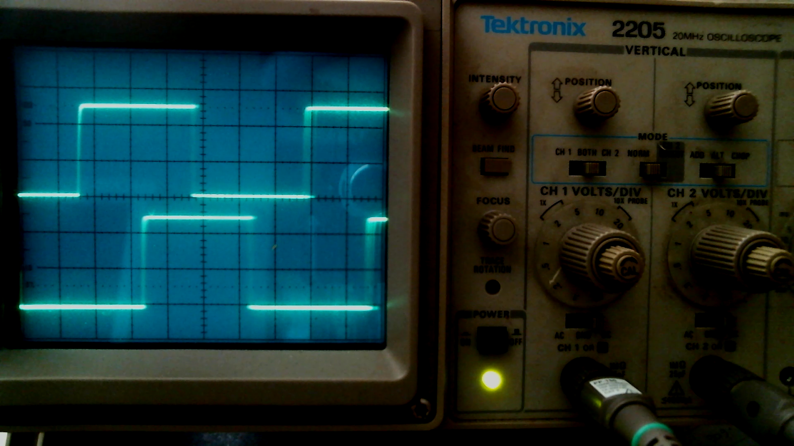
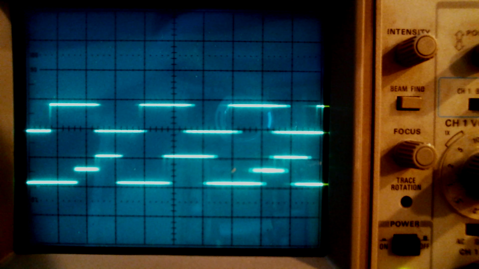
I hooked up the oscilloscope and got decent looking signals on both the signal wires.
So then I tried powering the motor. It wouldn't turn with a single AA battery, but two did the trick.
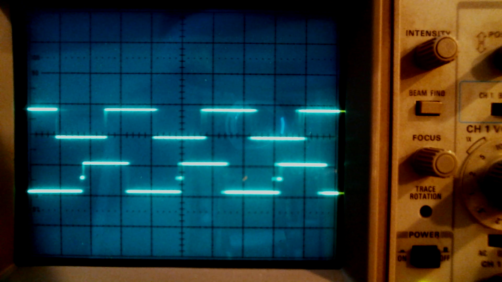
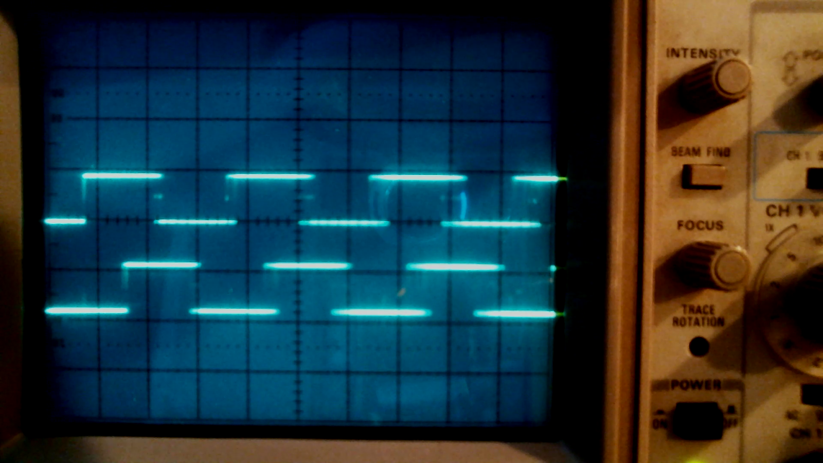
These are the scope traces, one in each direction.
Direction 1:
Direction 2:
The bottom trace is the same for both, but the top trace is opposite, comparing the two pictures.
Success. This means I'm getting proper quadrature readings at just 1.8v. Oh, and apologies for the misaligned trace lines on those. I've since adjusted the rotation.
Now, I have to figure out how to level-shift these back up from 1.8v to a voltage that's appropriate for Arduino (or whichever processor I end up using), and do the same for each axis motor.
Level Shifters
Ah, how to choose? There are various devices out there. One Arduino page suggests the TXB0108.
Another suggestion is a USB-serial converter. I actually have one of those from thrifting, but I don't have two, and they're rather bulky.
Sparkfun has this nice little board based on the BSS138
http://cdn.sparkfun.com/datasheets/BreakoutBoards/BSS138.pdf
with associated guides, but it seems geared toward 3.3v-5v shifting. It doesn't really explicitly talk about 1.8v.
The TXS0108E 8-Bit Bi-directional device looks promising.
The 74LV1T34-Q100 available at mouser only allows for 1.8v to 3.3v, and then 3.3v to 5v. If I'm reading this right, I suppose I could put a couple of those in series at the cost of additional lag, and lag is 20ns/V (30ns for step 1, 34ns for step 2, total 64ns. At 38kHz, we're talking 26us period, so orders of magnitude higher than the lag.
Getting a step-wise set of components would be good for future use. It's more generally useful if I mess around with 3.3v-5v stuff.
But the problem right now is that the 74LV1T34-Q100isn't really available due to pandemic backlogs.
digikey is showing a TI LSF010x 1/2/8 Channel Auto-bidirectional. It seems to meet all the functional needs, but several of the form factors (SON, SM8, etc.) don't match up with what I'd like (PDIP, SOIC). However, VSSOP and TSSOP, according to
https://en.wikipedia.org/wiki/List_of_integrated_circuit_packaging_types
may work. VSSOP appears to be equivalent to MSOP, and both MSOP and TSSOP could have 0.65mm pin spacing, and that just might work with the breakout boards I got recently.
3/24/22 update - powering the encoder circuit
I tried powering the 1.8v rotary encoder circuit by using a 5v power supply and a voltage divider (1k and 470 ohm resistors). But the light on the device didn't come on. After some consultations with friends, I've learned that voltage dividers aren't good for powering a circuit like mine. They work well in situations where there's high impedance.
I'm now on a path for getting a lower voltage power system going. In the end, I think I'll need three power sources:
1.8v for the rotary encoder circuit
5v for the microprocessor. (Or 3.3v, depending on whether I go to Raspberry Pi for this.)
Some higher voltage for powering the motors. Those ran on 3v battery power, but I probably can go higher, especially given that the original machine's power supply was spec'd at 18v, 2.5a.
For the 1.8v power, suggestions currently are:
LM317A adjustable voltage regulator, which seems easiest to wire and has a very wide Vin-Vout range
LD1117 adjustable output regulator (with Vin ranging 3.8v to 8v)
TC2014-1 low dropout, precision; packaging options may be an issue (SOT-23 might need a breakout board).
3/26/22 update - power, again, and PID links
I received a 5-pack of buck converters. "DC Buck Step-down Power Converter Board 5~16v to 1.25v 1.5v 1.8v 2.5v 3.3v 5v 3A" on eBay, or something similar. They tested out great. You bridge-solder one of the voltage selection pads, and it'll convert 5-15v in to one of the selected voltages out. I chose 1.8v for the encoder module, and it tested out at 1.818v on my multimeter. I also checked the signal on my oscilloscope, and it didn't show overshoot or noise.
I only have a few things I don't like about these boards. First, they're big. But that's kind of to be expected given how many options they provide. Second, the IN-, IN+, OUT- and OUT+ holes are really large, which made it unwieldy for soldering. One good thing, though, is that those holes land squarely on 0.1"-pitch distances. The length, hole to hole, is 1.1", and the width is 0.6".
I took a second one of these converters, and set it up for 5v.
Then, I soldered both converters to a breadboard. (Oops, I made the mistake of blocking the mounting holes.) The idea is that it'll take 12v in, convert it to 5v in the first step, and then go 5v to 1.8v in the second step.
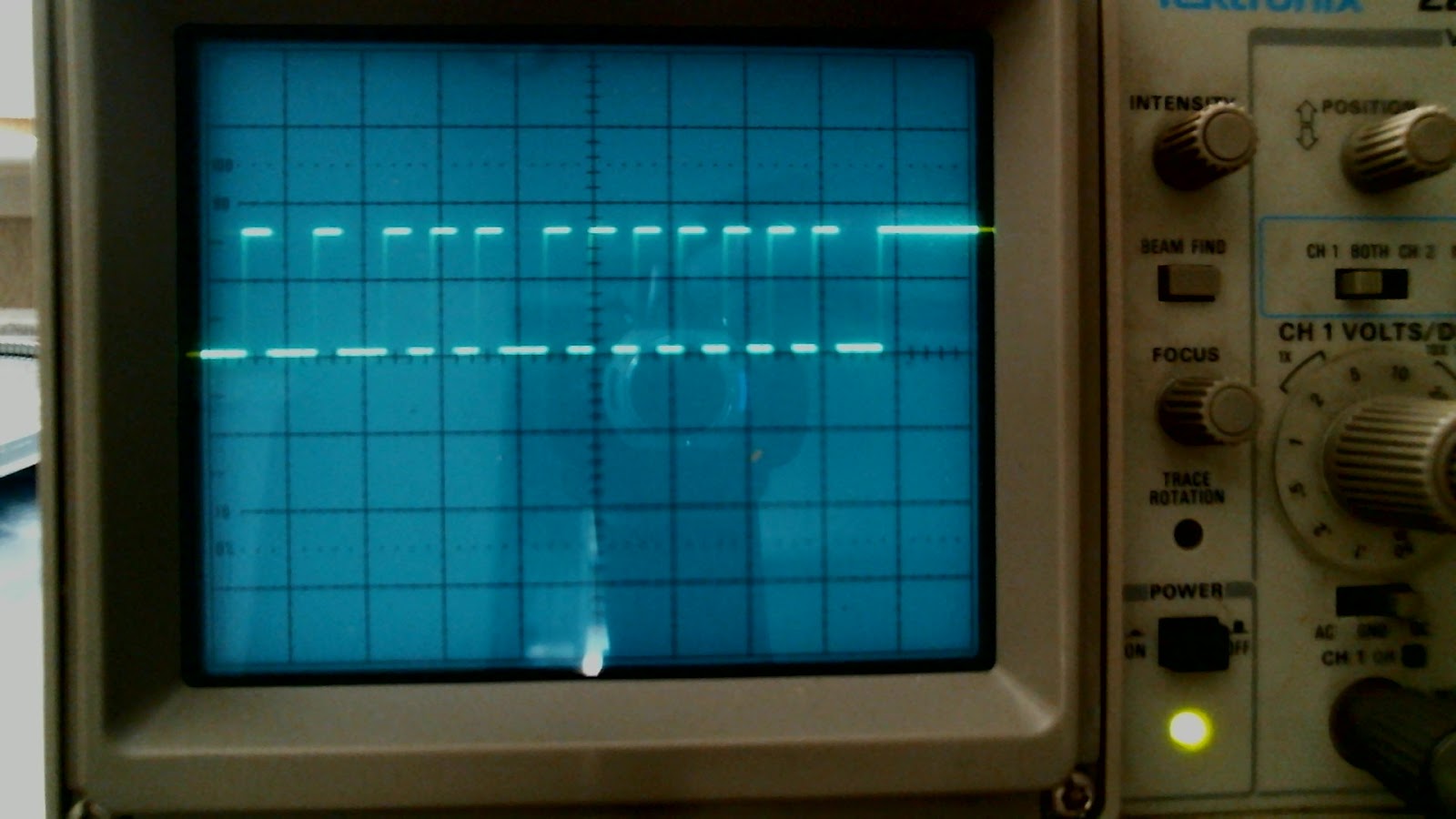
Once that was set up and tested, I wired the 1.8v output to the encoder, and then put the 5v to a built-from-scratch level shifter to bring the signals back up to 5v. The resulting scope shows it working quite nicely. This image is just for one encoder output pin, comparing the 1.8v output to the level-shifted 5v output.
Meanwhile, in PID reading, I found the video that appealed to me most, one from Curio Res:
https://www.youtube.com/watch?v=dTGITLnYAY0
That one has a sibling video that shows two axes being controlled:
https://www.youtube.com/watch?v=3ozgxPi_tl0
A more advanced page is at
https://www.robotshop.com/community/blog/show/using-the-arduino-pid-library-for-precise-position-control-of-x-and-y-axis-on-repscrap-printer
and it references
http://brettbeauregard.com/blog/2011/04/improving-the-beginners-pid-introduction
Eventually, I'd like to get to that level.
Next steps
- Maybe build the level-shifter circuit on a soldered breadboard
- Build a second level-shifter circuit. (In the end, I'll need four. Two signals for each encoder.)
- Or maybe wait until I get level-shifter modules in the mail.
- Start PID coding.
3/27/22 - level shifting noise
I received a set of boards for doing level shifting. They have a Texas Instruments YF08E aka TXS0108. At least, that's what the order on eBay said it was. I've seen some posts where a TXB0108 has restrictions that the TXS0108 doesn't face.
The actual markings on the board say YF08E / 7AKG4 / AE8C
In any case, it's a breakout board that lets you have access to eight "in" channels that can be leveled up to eight corresponding "out" channels. You can, for example, level up from 1.8v on the "A" side to 5.0v on the "B" side.
What I observed, though, was significant noise.
Here's what the 1.8v signals from the encoder looked like when shifted to 5v with a 33pF capacitor across ground and the level shifter's input lines.
I tried some other capacitor values to see how they'd behave. (Again, caps here are going from ground to each of the encoder signal lines, which are the input lines for the level shifter.)
At 1nF, I got this:
And at 8nF, I got this
I didn't start seeing smooth-ish signals until I'd gone up to 0.1uF capacitors, and even then I was seeing some oddities on rise and fall. I'm thinking these signals might work for a microprocessor, though they're still noisy.
However, at 0.1uF caps on each of the rotary encoder outputs, that meant I was changing their shape, and possibly affecting max attainable frequency. So, here is what the 1.8v lines look like clean:
and below is what they look like when using 0.1uF capacitors:
Methinks that ain't great.
The TXS0108E (possibly also the TXS0108E-Q1) datasheet calls for a 0.15pF cap and 1M resistor in parallel to ground from an output signal, and I didn't have that. So perhaps if I add that, I'll get better results. But, I didn't do that for the more successful results shown below, either. In all these measurements, I just stuck the oscilloscope probe on wire from a given pin.
Back to plan A: build the level shifter circuit
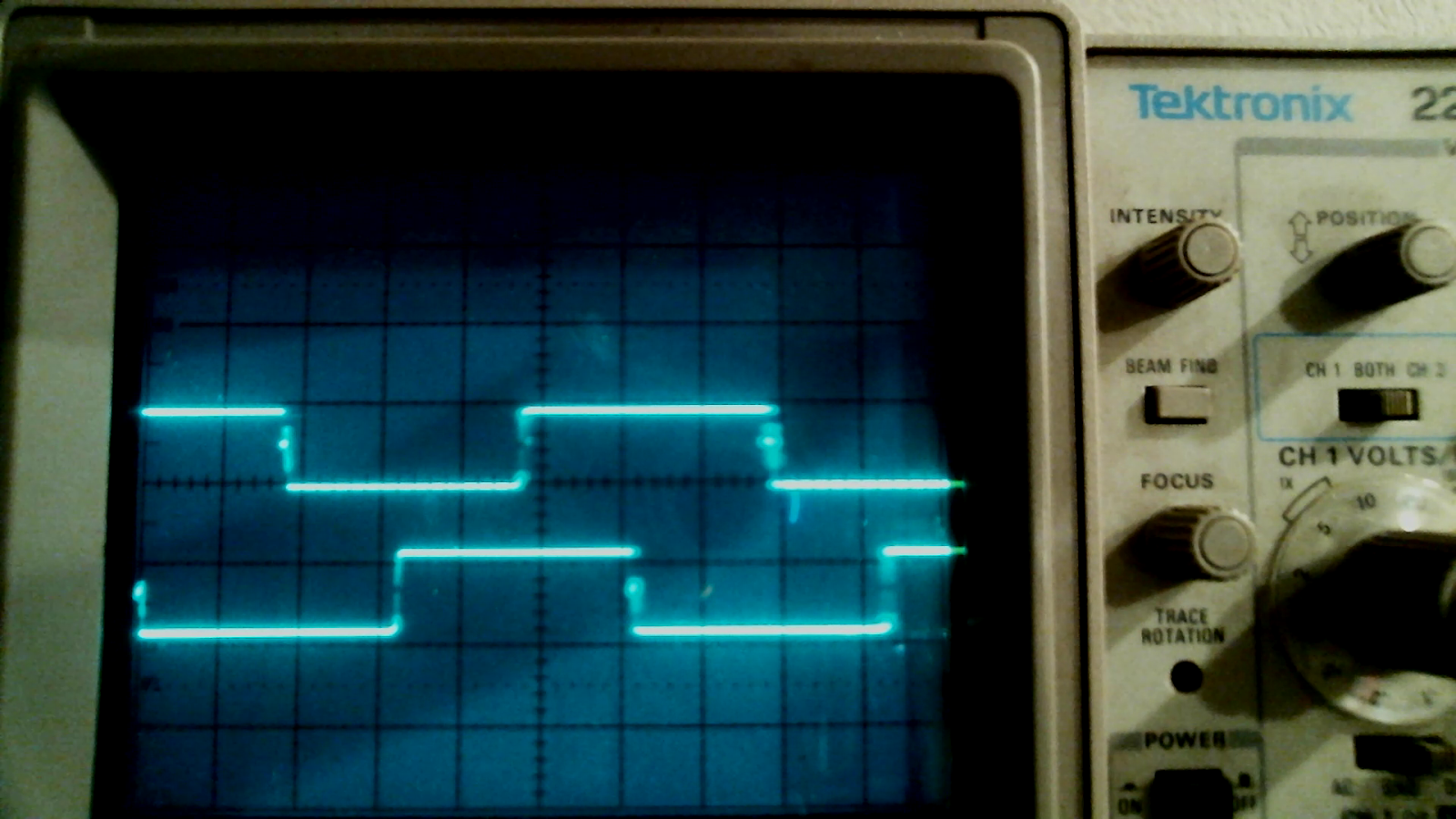
I went back to plan A, using the hand-assembled level shifter. These are the signals I got out of it without any caps:
So those look quite clean, though the level shifting circuit is way bigger than TXS0108, even with its breakout board.
For now, it seems like the simplest thing to do would be to build out the level shifting circuits on my own.
By the way, you might notice a good amount of horizontal jitter in the signals above. That jitter is lessened depending on orientation of the motor, so it could just be due to non-concentricity of the encoder wheel, and/or physical vibrations when the motor is running.
At this point, I have power and 5v signals coming out, and a motor driven at 3v battery power. I just need a proper PWM motor controller board (I must have one somewhere in the garage) and then I can get to Arduino PID coding and testing.
PID motor control
I tried building the PID motor controller as described on earlier links, and it worked pretty well. But I usually would run into oscillation at the target point.
I also started with just 6v and then 9v power to the DC motor, and that worked pretty well with an unloaded motor. But when I put the motor back into the machine, I would regularly fail to reach the target position unless I was at 12v or higher. (And since I'm running my power to the buck converters, I don't dare go near or above 15v.) Further, when I got to 12v, it got really noisy.
Finally, the PID curve that I plotted would vary in accuracy based on load. So, if I have the machine loaded with a mat with different materials, I think the voltage (or PWM?) would have to vary based on resistance faced by the material found.
So there's a tradeoff. I need power to combat the physical resistance of the machine (in my case, all the movement of the paper feed mechanism plus material), but too much power makes for too much noise.
I have to think of what kind of accuracy I really need.
The motors are geared, and the encoder has lots of steps, so maybe
there's a tolerance such that if you're within 100 steps, you're "close
enough" for arts and crafts.
Below is a snapshot of the Arduino plotter. The blue line shows the target position to move to, and the red line is the actual step count. If I recall, this was unloaded at 8v power, and the P-I-D values were something like P=1.0, I=0.0001, D=0.041. (There's quite a bit of overshoot/coasting in an unloaded system.)
The example above had two target points. It would start at count zero, then go to 800, and then 3400, and back again to 800. The graph shows that I got pretty good tuning with a few tries. It doesn't overshoot, and it does stabilize. (I changed the CurioRes code to stop printing location values, and brake the motor, if I'm within 10 steps of the target.)
One thing that the PID control was pretty good at was large numeric swings. In the plot above, we're marching some 2600 steps at a time.
What it's not good at is moving small amounts. Now, what is "small"? Time to actually count the gear teeth...
We start with the 96 holes in the encoder.
Those then drive an 11-tooth spur gear, which joins to the middle gear's outer ring of 66 teeth, so that's a 6x.
The middle gear has a joined 12-tooth spur gear. That drives the shaft gear, which has perhaps another 66 teeth.
So that's perhaps another 5.5 multiplier.
Moving one full shaft gear rotation takes perhaps 5.5 * 6 * 96 steps, or 3168 steps.
The feeder OD is something like 15.5mm, meaning, so circumference 2*PI*r = 48mm, so I think that means it takes about 66 steps to move the material 1mm.
I'll have to see if I can do such gradual motion. I know given a large swing I can get to within 10 steps. But with a small swing on a small step, I'm not sure if the motor will generate enough torque. The only way to do that is with a higher voltage for a brief moment.
Dual motion control
The problem with the PID experiment so far is that I'm driving one axis as quickly as possible (based on the Kp "proportional" factor and voltage and max PWM value).
What if I were to want to move X 500 steps, and Y 200 steps? Well, I think given the current implementation, I would start at (0,0) and try to move to (500,200), it would shoot quickly to somewhere near (200,200), and then draw a nearly horizontal line to (500,200). That's my guess.
So instead, I shouldn't just target (500,200) in one go. Instead, I could interpret individual steps along the way, as if it were a stepper motor. In that way, a vector from (0,0) to (500,200) would do a Bresenham kind of line pixellation, and incrementally change the PID targetX,targetY values fractionally.
If I can do this, then in theory I could have any other step controller (e.g., LinuxCNC) generate virtual steps, have the Arduino receive the steps and compute target locations, and have the Arduino signal "ready" when a target point has been reached, or error upon failure due to load (high error implies limit hit, or jam).
At that point, I end up with these questions:
- At max power (presumably 18v), what's the minimum controllable step count that I can achieve? And what's the lowest PWM setting I can do in order to get there?
- How does velocity figure into this? If I receive steps too fast for the Arduino to interpret, then I'll be throwing large delta target values and will end up with lots of 45-degree lines.
- How do I limit input? How do I signal to the step generator that I'm busy?
Some measurements
The power supply measures at 18.10v. As with most such supplies, the outer barrel is ground, and the tip is positive. The measurement is surprisingly close to the rated voltage printed on the label. I'm used to things saying they're some voltage, but measuring anywhere from 2 to 5v higher (!).
The motor unit had a bunch of test pads on the back which allowed easy soldering of test wires.
The encoder power actually measured at 3.173v, not the 1.8v I was using. I'm a little surprised because that means the diode would run at over 35mA with only a 64 ohm resistor in series and a measured 0.9v voltage drop.
On boot, the machine would do a slow and then fast paper feed movement (for me, "Y-axis"), presumably to eject any prior work. I didn't look at the X-axis motor.
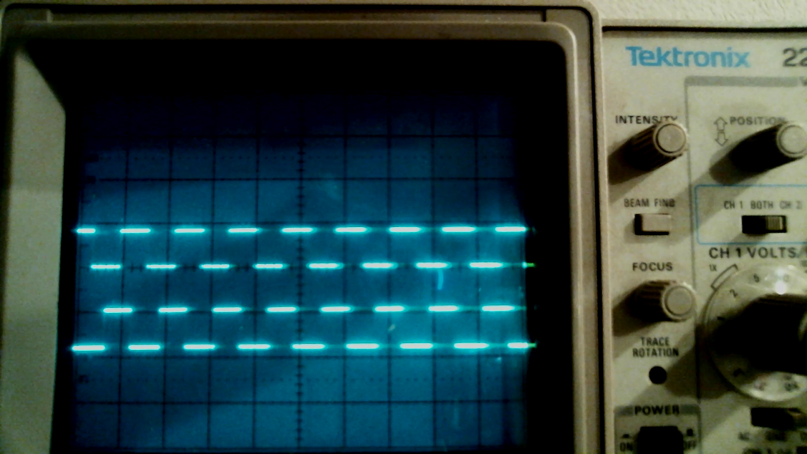
Here are oscilloscope trace snapshots with the scope set to 10usec divisions, the ground trace line set to the middle line, and voltage set at 5v divisions.
Slow
Fast
Both measurements above were taken in a no-load setting. The motor was disconnected from the left tower and related gear system, but was connected electronically to the motherboard.
The motor appears to be running at 18v. That's the important part.
As for the PWM signal, the traces aren't totally clean. A digital scope would give me a better ability to record the reading over time. Maybe being under load would help, too. Roughly, I think the "fast" movement is 8 microseconds powered within a 64 microsecond period. The "slow" speed appears to be half that at roughly 3-5 microseconds powered, so for convenience, I'll think of it as 4 microseconds.
Voltage regulators
I'm also setting up LM317s for doing voltage regulation. I found with a 1000/368 combination of resistors, I was getting about 5.1v out. I'll have to try some other values to get 3v for the encoder.
If I had a higher voltage power supply, I could also get regulated 18v output, but I think I'd have to be careful with the LM317's output amperage, and each might need up to 3v headroom (Vi-Vo) "to operate in regulation". So that would mean having a 21v or high, 2.5a power supply.
What kind of connector is that?
Determining what kind of connector hooks into existing boards is kind of a hard thing. I suppose manufacturers don't have to care about this so much. They specify both board header and wire harness connector, and load up on spares. For someone who is replacing or connecting to an existing board without any details, it can be tough.
I just found this site that has lots of pictures and specs. And, though I haven't signed up for it yet, you can download STEP files and other 3D renderings, as long as you're not a competitor, etc.
It looks like the connector I want for talking to the motor directly would be a JST-PH, at least according to that site.
https://www.jst-mfg.com/product/detail_e.php?series=199
Some terms to note in its "Further information" PDF: pitch, height, width, disconnectable, crimp style connector, through-hole, SMT, "no. of circuits", wire-to-board.
For the one in use on the motor, it's through-hole and side-entry. It comes up 5.1mm from the board, and is 13.9mm wide, 7.7mm deep. The width measurement aligns with the value shown for the header S6B-PH-K-S, though I'm not sure about its box size. I don't think it can be the PH "high box type", because that doesn't show a side-entry option.
S = side entry
6 = number of circuits
B = part name (header)
PH = series name
K = "clinched". I wonder if that's what's meant by having those little rectangular holes for holding the wiring harness to the header?
S = color (natural white).
Anyway, the point is that the jst-mfg.com site is great for being able to look up headers and connectors.


 connector removed")