I was given an inoperative little mini drone.
It has a little hockey puck activator like this:

I left that alone, but took the drone itself apart, and found a little lithium battery that probably had drained beyond rechargeability. I made a few attempts to recharge it, and gave up.
The inner circuit board was cute. It had an LED tower set up as a PCB mounted orthogonally to the main PCB. That LED tower is removed, but you can see the rectangular hole where it once was, and the solder points on the back where it was attached.

I've removed the motor mechanism and propellers. I also have de-soldered the IR LED receiver, and what appears to have been an IR LED transmitter. The transmitter pointed downwards and could have been used for sensing distance to the floor. (I don't know if this particular drone had side sensing ability.)
The IR LED transmitter is a simple two-wire device with a 1.0v voltage drop, determined by voltmeter testing.
The IR LED receiver was marked QCHA on the top, and I didn't find any clear specs on the web.

After doing a bit of track tracing (and roughly remembering how the device was originally oriented -- should have taken pictures before de-soldering) I figured the middle pin would be ground. It seemed to hit larger tracks.
I then made a crazy guess about which of the other two were power vs. signal. Both continuity-tested to points on the unlabeled, 4x2 SMD on the board. One touched the corner, and another touched one of the middle pins. Just based on that, I guessed that the corner-touching pin would be Vdd, and the other would be signal.
I put the device onto a breadboard as shown, but before applying any power, I just set my voltmeter in voltage mode, connected COM to the middle pin, and V to the blue wire. Nothing was connected to the red wire (presumed Vdd). Then, I pointed a random IR remote control at it, and pressed a button, and I could see a response in the voltage.
So with that, I set up the Eventer KPS305D power supply, measured its output at 3.3v, hooked up power to the IR receiver, and fired it up. Whew, no magic smoke.
I then attached checked the voltmeter and found it running at a steady 3.3v.
When I pointed the remote control at the device and did various button presses, I was the voltage drop to various levels, typically around 2.5v. Assuming my voltmeter is precise enough, I was getting various voltages on the different lines. I suppose that is indicative of the different wave forms -- perhaps even serialized binary values -- generated by each button.
So, now on to scoping it and seeing how it behaves. I know, lots of people have done this IR stuff before, and there are libraries. But I wanted to see if I could do this on the cheap with a salvaged receiver.
My main surprise thus far is that the signal line was giving me a steady 3.3v but then maybe it means there's a pull-up built into the device. Or, it just means that I really should put in a pull-up or pull-down of my own. I'll have to go read some specs to get a better guess as to what device I have.
Which device?
The Vishay TSOP34438 (TSOP344 and TSOP348) seems to have the same pinouts and form factor as the one I have.
The suggested circuit diagram on its datasheet suggests that the OUT pin is connected directly to the receiving microprocessor, and an internal 30k resistor between Vs and OUT is built into the device. So that makes me comfortable that I'm seeing the voltage value sitting at Vs when idle.
The remote control I was testing with was a Sony Audio System RM-S102. I suppose if I look more closely at it, I can figure out the carrier frequency (30, 33, 36, 38, 40, or 56 kHz) and thereby nail down the more specific IR receiver module. Or, I can just be satisfied that it appears to react to that remote control, and play with it.
The application circuit on the provided diagram suggests R1 and C1, but says I should choose them to "reduce supply ripple for Vs < 2.8V". Since I have Vs higher than that, I think I can do without R1 and C1 entirely, though I want to see the signals on a scope, and see if there's too much noise.
Next steps
1. Plug it into a scope and see what happens
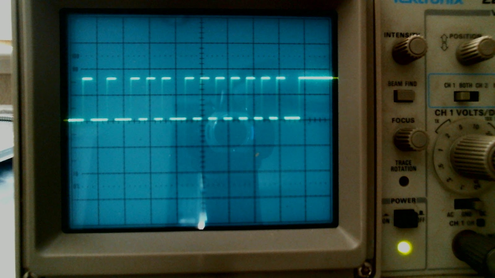
Yep, getting clean readings. I took these pictures using a :Logitech webcam pointed at the oscilloscope and using the Microsoft Camera app. It puts pictures into the Pictures\Camera Roll folder. Because of how the scanline traces run through, and the brightness of my environment, I took about 6 to 8 pictures per shot, and picked the one that showed the trace best.
Examples of buttons and their IR readings:
POWER:

PLAY:

PREV:

NEXT:

VOL_UP:

VOL_DOWN:
STOP:

The drone starting fob gave a momentary wave form:

2. Plug it into an Arduino and see if I can get a simple sketch together (using examples provided by many others, and an existing library) to reuse the buttons of the remote control.
No comments:
Post a Comment