I picked up a copper-ish music box the other day. It's made of decorative sheet metal and depicts a horse running out of a barn. As the music box plays, if the music box could play, a horse and cart come out of a barn door and run around. The barn door serves as the stopping mechanism (whereas for other music boxes they usually stick something in the way of the governor).
 |
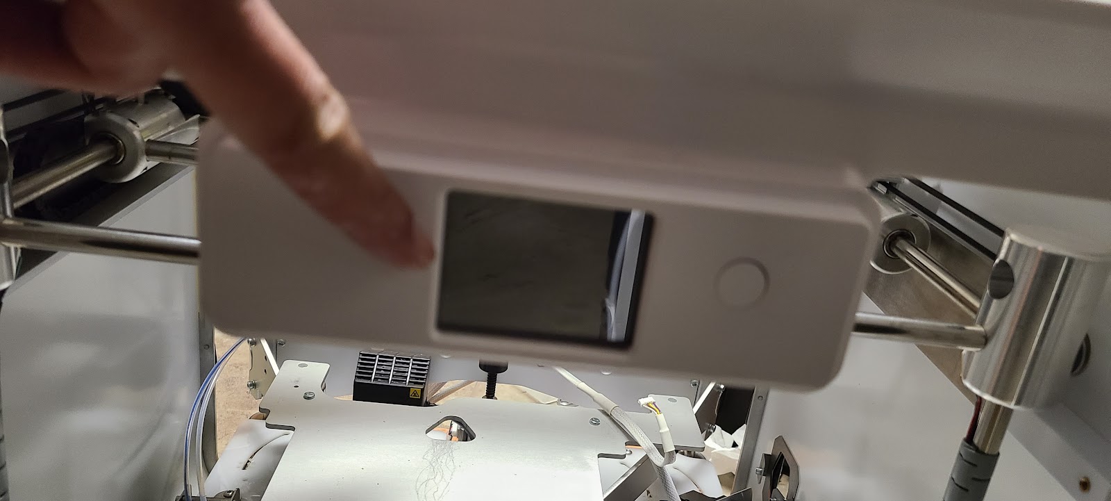
Tin (copper plated) horse music box, "King of the Road" with mechanism removed
|
The problem with the one I got was that the music box mechanism didn't work. You'd turn the crank handle, and it wouldn't click. After enough of a turn, you'd feel the tension increase a bit, but then it would "slip" and go back to feeling loose.
The initial cleaning and disassembly was easy. I did a quick wipe-down of the exposed surfaces, being careful not to catch the cleaning cloth on any metal hook points. As I was doing this, I noticed that the underlying metal isn't actually copper. The whole thing appears to be electroplated in copper in some way, and then left looking "rustic".
The next step was removing the music box assembly. To get there, I removed the "horse assembly" from the music box. As it turns out, that part is held on in a "righty-loosy" threading, so I heated up the joint area (just in case there was glue on there), and then rotated the assembly clockwise to take it off.
To remove the music box wind-up handle, I was able to find a way to hold the opposite end of the crank
shaft. Then, I could rotate the handle counter-clockwise and remove it. After that, it was just a matter of taking out a couple of screws that held the mechanism to the barn.
This next picture shows the horse assembly reattached to the music box mechanism after both parts were removed from the barn.
 |
Horses and cart connect via an arm to the mechanism (righty loosey)
|
The mechanism was a little dirty, so I did some careful cleaning of the joints. Its spring housing is marked "Tokiwa", "JAPAN", with what appears to be an image of Mt Fuji.
Unlike many modern, cheap mechanisms, the spring housing is metal, and the initial multiplying gear is metal with a very fine pitch. The only plastic gearing piece is the one that connects to the wormgear / governor.
Besides those characteristics, the main oddity of this mechanism is that the "music barrel" (the cylinder that has the pegs that pluck the tines) has a shaft extending outward. It's that shaft that connects to the horse assembly. It's held in place by a bushing, and the bushing is held onto the assembly with a set screw.
Remove the set screw, and you can pull the bushing out (along the axis of the spindle).
 |
With set screw loose, push barrel assembly away from spring housing...
|
 |
...and slide bushing off
|
Then, the barrel/spindle assembly can be rotated out by sliding the spindle out through a gap along the side of the mount.
 |
Pivot barrel through slot
|
 |
Barrel and bushing removed
|
I assumed the spring was broken or otherwise disengaged from the mechanism. So, manually turning of the barrel was feasible (and wouldn't overwind or underwind the spring). It sounded like it would play "King of the Road".
I removed the barrel and bushing from the mechanism, and then wasn't sure what step to take next. I had hoped to take the barrel to another, similar mechanism, but ran into these differences with my little collection of mechanisms:
- Wrong gear. The one I have is fine pitch and metal, and I only have two others like it. Most others are plastic and have fewer teeth.
- Mount has the wrong hole diameter for the spindle. This one has to have enough room for the bushing, and needs a set screw to hold the bushing. All my other mechanisms have a hole that's smaller.
- Needs a gap for the long spindle end. Since this one has such a long spindle end, it can't just be threaded through the mount hole. It needs a slot chopped out of the side, and the slot has to be at least as large as the spindle (not including the bushing).
All in all, that left me thinking: maybe I can fix the spring assembly.
I looked around and didn't find any web pages that explain how to remove and replace the spring housing from a music box. From what I've seen, all mechanisms, whether old or new, have the spring housing riveted onto the mechanism frame.
I chose to drill out the rivets. I had no idea what drill size to use, but picked a small one, put it on the drill press, added some WD-40 to lubricate, and gently went in. Eventually, it got in, at first piling up a "splash" of metal, and then eventually yielding metal ribbons. I didn't drill all the way through, but was sure to drill deep enough that I could go through later if I wanted. I used flush cutters to remove the "splash" and filed down what was left.
 |
Heads of rivets (that held spring housing down) drilled and filed off
|
In retrospect, I probably should have tried to file (or grind with a Dremel) the rivet heads down slowly, instead of drilling. I got one of the rivet holes pretty well centered, but the other one didn't go so well.
With the rivet heads mostly gone, I was able to pry up the spring housing. It popped off one side pretty easily, and with some stronger encouragement I was able to get the other side off. Fortunately, the housing wasn't glued down elsewhere.
I thought perhaps once I had it off, the spring would want to jump out and make my life really difficult. But, there are still other pieces in there. The way it's assembled, there's a crank shaft, a plastic piece that helps the "click" mechanism (call it a ratcheting mechanism), a beveled gear, and the spring. The crank shaft hooks into the spring, when it's working properly.
The first obvious problem was that the ratcheting mechanism had broken into two pieces.
 |
Broken ratcheting thing
|
Then, I found that the spindle and beveled gear weren't engaging the spring. I removed the beveled gear, and then saw that the inner loop of the spring simply wasn't within reach of the spindle's hook.
I took out the spindle, and then gently nudged the inner coil of the spring more towards the center. I did this by sticking a very small screwdriver between the spring coils, and just prying the inner coil section inward. I wasn't sure if it would bend enough for that, and I was afraid I would break it. But, just a little bit of bending was needed. After enough of that, I was able to put the spindle back, and feel it hook on.
With that in place, I was able to put the beveled gear back on. This kept the hooked spindle and coil in place.
The ratcheting mechanism is a whole different problem. I'm not sure what kind of plastic it's made of, but it seems like it has to be tough yet flexible -- kind of like cutting board plastic. Initially, I tried using CA glue (superglue) but was pretty sure it wouldn't work, and it certainly did not work.
 |
Glued ratcheting thing - looked promising but couldn't take the strain
|
Then, I tried the "soldering iron" approach, melting edges across from one piece to the other. That also failed.
So now, I'm considering manufacturing a replacement by 3D-printing in ABS, or milling one out of cutting board plastic. I'm starting by supergluing the halves together again. That will let me place the piece in a scanner, and then build a model in Fusion 360.
Some measurements:
- Spindle OD: 4.5mm
- Spindle OD with nub: 5.53mm
- Channel Depth: 3.3mm
- Outer Edge: 16.3mm
- Outer Engagement (tooth tip to tip across center point): 15mm
- Disc OD: 13.5mm
- Disc OD to pawls: 14.6mm (With non-pawl radius at about 13.5/2mm, or 6.75mm, the pawl radius is about 7.85mm, which is more than the Outer Engagement radius of 7.5mm)
- Disc thickness: 2.9mm (which is less than Channel Depth, so that's good)
- Arm thickness: 1.5mm (gives a gauge of how much plastic is bending)
- Sweep to pawl: about 120 degrees
I'm also thinking that I could find a replacement in some other music box mechanism, but these mechanisms have evolved, too. This great YouTube shows the inner workings of a music box, and the newer ones have multiple catch points. Mine only has one catch point, and one connection point to the spindle.
Since the mechanisms have evolved, I'm afraid the only source for a replacement piece would be one of my other old, metal music box mechanisms. I only have two left. One plays the Happy Birthday song, and its housing seems smaller and incompatible. The other one plays "Somewhere My Love" from Doctor Zhivago, and it just feels too pretty to hack apart. It's hard to want to sacrifice "Somewhere My Love" for "King of the Road".
Simulation
While I pondered how to repair the ratcheting mechanism, I decided to revive an old project idea: simulating a music box in software using sampled sounds.
Having removed the barrel and spindle separated from the mechanism, I had direct access to the tines, so I could pluck them individually. In this music box, there are 18 tines, and that is typical of little music boxes. I could pluck each one with the tip of an old, fine-tip nail.
I tried to get a decent sound recording environment, so that meant removing batteries from noisy clocks in the room, and turning off the forced air heater. The only other controllable ambient noise at that point was my computer fan, but it was negligible and non-spiky.
I put the mechanism atop a wooden box to get some sound resonance, and stuck my phone inside the box cavity. Then, I just recorded a video with all the sounds. The phone recorded an .mp4 file.
Along the way, I found that some of the tines produced the same tone. It was set up this way so that repeated notes could be done in rapid succession. (Otherwise, the tine could hit a barrel peg while still vibrating.)
I transferred the .mp4 file to my computer, and then loaded it into Audacity (after having first set up ffmeg for Audacity). (I also got to fix the clocks that I'd disabled at this point.)
That allowed me to look at the different waveforms for each pluck. I range-selected the best of each one, and then copied and pasted that into a new document. Then, I mixed the stereo tracks to mono, hit Ctrl+A to select all, and did a Effect/Amplify to get consistent volume. (There is one track where a few initial points were so loud that they needed special trimming to get auto-amplifying to work.) Then, I zoomed in and trimmed off the lead-in silence, and set the overall duration of each track to around 2.5 or 3 seconds.
In some cases, additional silencing was required, where unusual background noise was seen. That just amounted to range-selecting an area and hitting Ctrl+L to silence the track.
I exported each tine waveform to its own .wav file.
In general, I named the files based on the tine that was plucked. I chose a numbering system where 1 was the longest tine (lowest tone), and 18 was the shortest. Afterward, I also compared the sounds to an online tone generator (e.g., https://www.szynalski.com/tone-generator/) so I could know which octave and note was being played.
Even without knowing the specific note, I could watch the barrel pluck the tines to know what was being played, and roughly when.
To get a better idea of the timing of the notes, I looked at online sheet music on different sites.
Thoughts on wave combination
I ran across some pages that discussed the pydub module. It looked promising, given that it could overlay one waveform on another.
My first thought on how to combine the sounds was like this:
- Each tine is its own waveform
- A "pluck" of the tine happens at some time n
- The next pluck might happen at time m.
- Set up a silent wave of time n
- Save lastTime as n.
- Append the tine's waveform and get its duration d
- Go on to the next occurrence of this tine (time m)
- If lastTime+d > m, then truncate the built waveform to lastTime+d, and append m. Set lastTime to m.
- If lastTime+d <= m, then add a silent waveform to bring the length to m, and then append.
With that approach, I'd set up 18 songs, one per tine. Then, I'd overlay all 18 at the end to make a combined song.
In experimenting with that, I found that the AudioSegment.overlay() function in pydub was doing strange things to the overall added wavelength. For example, if you overlay a short waveform atop a long one, it truncates to the length of the shorter waveform, thereby risking loss of long resonance.
Second approach to wave combination
As it turns out, the AudioSegment.overlay() function takes a position argument that does what I want without all the complexity above.
- Create one big silent waveform
- Go through the song one note at a time, knowing each note occurrence's measure number, start position within the measure, and tine number (or tone).
- Compute a time offset based on measure and within-measure position.
- Overlay the tine's waveform on the big waveform
- Repeat
This approach also allows for chords (just have two tones played at the same time point), and arpeggios (allow a slight offset).
Initial overlay experiment
As an initial experiment, I wrote the following Python code. It does these things:
- brings all file names into an indexable array
- sets up the long, silent waveform
- walks the tines in reverse order (so, highest tone down to lowest)
- overlays that tine's sound onto the main waveform
- positions the next waveform 60 milliseconds later
- exports the waveform in mp3 format using 128kHz frequency.
Song Experiment 1
My next step was to construct the actual song rendering. I also went to a python dictionary approach, rather than using an indexed array. Eventually, that will allow me to reference notes by name, rather than number.
For the timing, I set up an array of elements, each of which represented (measure number, eighth note number, tine number). The measure numbering starts at one. The eight notes are numbered 1 through 8, and allow for fractions. The choice of eighth notes just worked well for timing representation because the King of the Road music is written that way. The fractional timing of the eighth notes allowed for things like grace notes and arpeggiated chords.
Here are the tones:
filemap = {1: "1 D5.wav",
2:"2 E5.wav",
3:"3 F#5.wav",
4:"4a G5.wav",
5:"5 A5.wav",
6:"6b D6.wav",
7:"7 D6.wav",
8:"8 E6.wav",
9:"9 F#6.wav",
10:"10 F#6.wav",
11:"11 G6.wav",
....
18:"18b E7.wav",
19:"19 high F#7 from 3.wav"
}
Note how the "F sharp octave 6" value appears on both tines 9 and 10.
Here's a snippet of the "song" sequence:
song = [
[1, 3, 16], # Trail
[1, 4, 9], # ers
[1, 4, 13], # ers
[1, 6, 3], # for
[1, 6.125, 10], # for
[1, 8, 5], # sale
[1, 8.125, 8], # sale
[2, 3, 9], # or
[2, 4, 11], # rent
[2, 4, 13], # rent
[2, 5, 4], # embellish
[2, 6, 3],
[2, 8, 2],
[3, 3, 8], # rooms
[3, 3, 15], # rooms
[3, 6, 13], # to (F)
[3, 7, 14], # le- (G) let
[3, 8, 12], # -et (F)
[4, 1, 6], # fif (D)
...
]
(The tone notations above, e.g., D, F, and G, are based on what I saw on sheet music. The IRL tine tones actually are about three half-notes higher. For example, tine 3 on sheet music for the word "for" is a D on sheet music, but is "F#5" in reality. The beauty of music transposition is that if everything shifts an equal number of half tones, it still sounds correct, but just in a different key.)
With all that, all that was left was to define an overall tempo, which I chose to mean "number of seconds per measure".
Then, the computation of the time offset since start was easy:
time = ((measure-1) + ((beat-1)/8)) * tempo
millis = int(time * 1000)
Then, I overlay the tine's waveform at that point in time (in milliseconds).
wavSeg = AudioSegment.from_file(filemap[tine], format="wav");
newSeg = newSeg.overlay(wavSeg, position=millis)
Click here for the non-swing song
Song Experiment 2
The result of Song Experiment 1 was good, but not great. The song is meant to have a swing beat. Think of each pair of eighth notes taking up a quarter note of time. In strict timing, the first happens on beat (at time zero), and then other at time 1/2 (halfway across quarter note, i.e., at the 1/8th mark). In swing beat timing, the first happens on beat, but the second is 2/3 across the quarter note.
So, to get a swing feel, I just changed the timing computation based on which 8th note timing was in play.
if ((int(beat) % 2) == 0):
# even beats get "swing" feel
# 2,4,6,8
# become 1.33, 3.33, 5.33, 7.33
# and then divide by 8.
beatswing = beat - (2/3)
beatpos = beatswing / 8
else:
# odd beats are right on time
# 1,3,5,7 -> just do n-1 over 8.
beatpos = (beat - 1) / 8
time = ((measure-1) + beatpos) * tempo
millis = int(time * 1000)
With that in place, the overall song sounded much better!
This is the "swing" rendition
What's next
I still want to machine/mill/3D-print a replacement ratchet piece and see if I can fix that original spring assembly.
If not, I may see if I can switch to an electronic representation of the music box, but still replicate the wind-up feel.
A 3D-printed replacement
I'm amazed.
I was able to print a replacement for the ratcheting thing. It took me five iterations to get the measurements working. In the end, I had about 0.4mm compensation for shrinkage of the hole around the inner spindle (tight squeeze at 0.3mm), and a 1.5mm radius on the hook nub area, where I'd measured 1.03mm. I also modified the pawls to extend much farther outward, partly because the original sizes barely caught or missed the teeth, and partly because the 0.6mm nozzle in my 3D printer lost precision on the sharp tips of the pawls.
This is the sketch
and this is what the extrusion command looked like:
After extruding, I did some fillets at various points. This is what the model looked like afterward.
The slice in PrusaSlicer looked like this:
After printing it, I had to file the inner nub hole a little bit. I could slip the piece over the inner spindle easily, but getting it onto the nub took more force. It ends up being a tight fit, but it didn't break as I forced it on.
With this in place, I could wind up the spring again! So I reassembled everything. I'm surprise that it hasn't broken so far. What I have to do now is reattach the spring housing to the frame. Without that, the tension sometimes causes the whole spring housing to jump off of the rivet posts.
I wound it up and was able to hear the music box's full song for the first time since I got it. It's not perfect. The pawls slip sometimes (I'm not sure why). But it's close enough at this point for me to close up this project.
3D-printed part, Revision 6
Of course, I couldn't leave this project alone, knowing that the ratchet wasn't catching properly.
I took apart the spring assembly again, and got some pictures to add earlier in this write-up, and then took a closer look at why the catch was failing.
As it turns out, the pawls were engaging well when hooked onto a catch, but the design collided with a catch on halfway points (half clicks, if you will). Pictures to help explain...
This is an example of good engagement, where the metal catch is hooked into the midway point of the pawl.
However, if I do a "half click", both tips of the pawl should reach the edge (in-between metal catches). It's not doing that in the v5 design, because I had too much material in the way.
I finally paid attention and found that there are 15 teeth in the outer ring, meaning they're space 24 degrees apart.
I updated my design to add ticks every 24 degrees, and then modified the pawl catches to match.
With rev 6, this is what it looks like when the pawl is fully in-between metal teeth. Now, the outermost pawl tooth is reaching all the way in, and engaging the metal catch well.
and this is what it looks like at the halfway point. It doesn't show well in the picture, probably because of messy 3D printing, but it works well.
Now, to do a super precise job, I'd model the actual teeth, and rotate my model in F360 to make sure it's behaving properly, find some way to model the pawl arm and teeth position under tension, and fix the pawl teeth tips to more closely represent the 3D-printed result (tips must really be curved due to nozzle dimensions).
But now that it's not skipping, I think I'll go back to the issue of reattaching the spring housing. I'm thinking a solder blob or two might work, if I can heat up the metal components enough to receive the solder.